Electron scanning microscope and image generation method
a technology of electron scanning microscope and image generation method, which is applied in the direction of electric discharge tubes, instruments, measurement devices, etc., can solve the problems of liquid specimens, biological/chemical specimens, etc., damaged or changed in state by vacuum, and achieve the effect of reducing the frequency of isolation film replacement, and reducing the probability of isolation film damag
- Summary
- Abstract
- Description
- Claims
- Application Information
AI Technical Summary
Benefits of technology
Problems solved by technology
Method used
Image
Examples
example 1
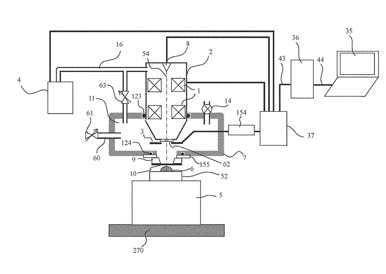
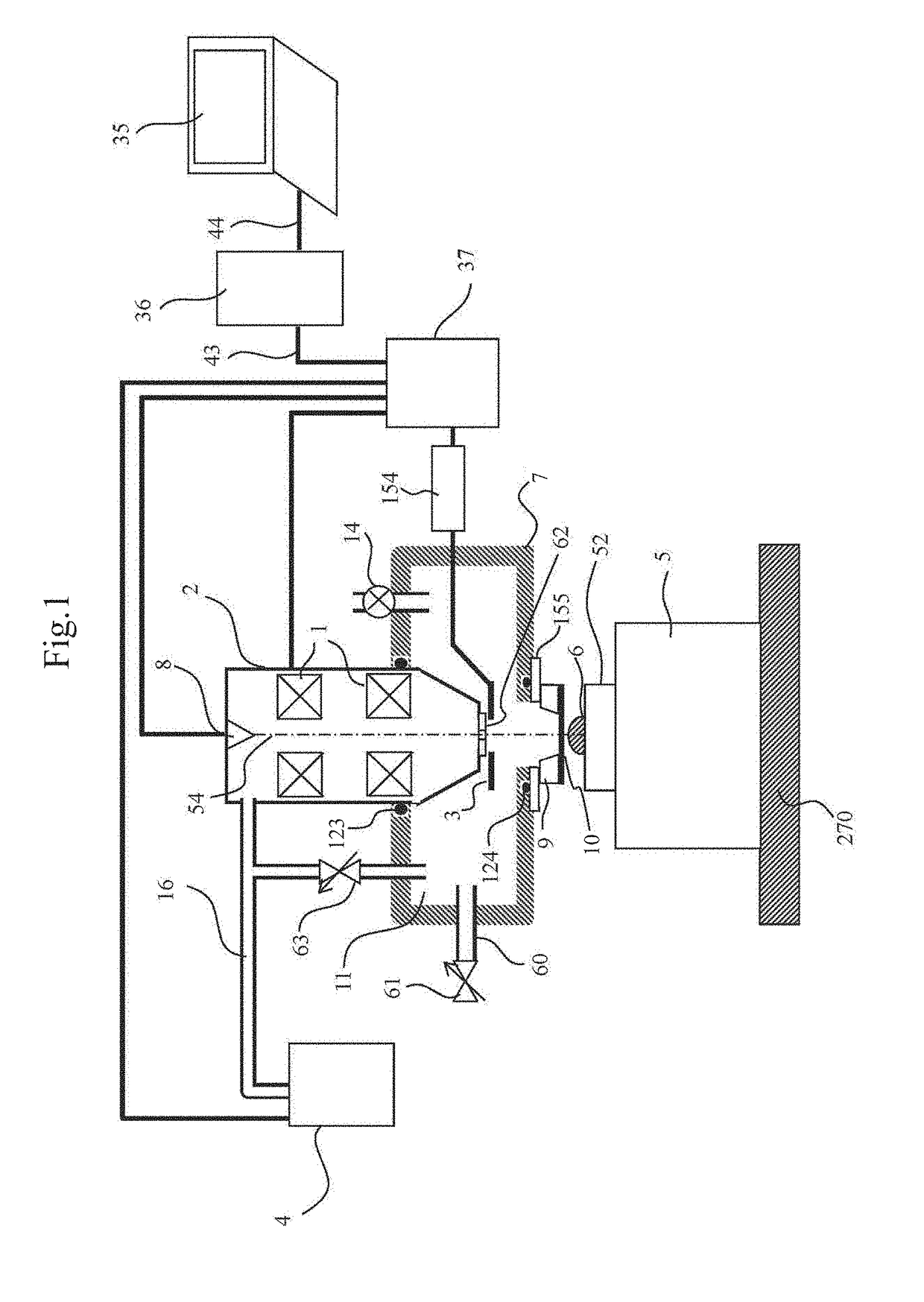
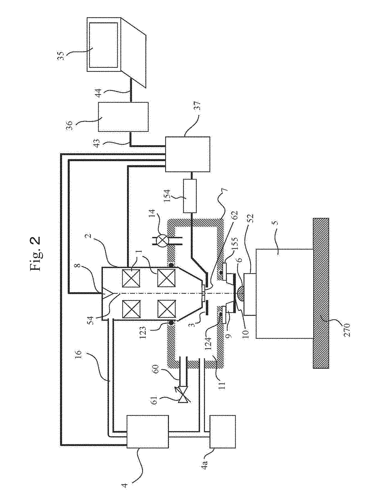
[0029]In this example, a basic embodiment will be described. FIG. 1 shows a view of the overall configuration of the charged particle microscope in this example. While the example below is described on the assumption of a scanning electron microscope, the invention is not limited to this, as described above.
[0030]The charged particle microscope shown in FIG. 1 is mainly made up of an charged particle optical lens barrel 2, a chassis (vacuum chamber) 7 which is connected to and supports the charged particle optical lens barrel 2, a specimen stage 5 arranged in an atmospheric atmosphere, and a control system which controls these. When the charged particle microscope is in use, the insides of the charged particle optical lens barrel 2 and the chassis 7 are vacuum-pumped by a vacuum pump 4. Start and stop operations of the vacuum pump 4 are controlled by the control system as well. Although only one vacuum pump 4 is shown in the illustration, there may be two or more vacuum pumps. It is...
example 2
[0059]Incidentally, in the charged particle beam microscope which enables observation under atmospheric pressure, the observation field of view is limited by the opening area of the isolation film 10. That is, while the isolation film 10 is very thin because of the requirement of transmitting electron beams, the area of the isolation film 10 needs to be very small in order to seal the vacuum with the sufficiently thin isolation film. For example, the area of the isolation film 10 is 250 μm by 250 μm and the area of the isolation film 10 is set to be small enough to endure atmospheric pressure. Thus, observation is performed within the range of the opening area. Therefore, in order to observe a specific place on the specimen 6, the field of view is repeatedly moved to search for the observation target site. This operation is very complicated, significantly impairing the convenience of the charged particle beam microscope which enables observation under atmospheric pressure.
[0060]In t...
example 3
[0072]Hereinafter, an apparatus configuration with which a specimen can be observed easily using a common charged particle beam apparatus will be described. FIG. 6 shows a view of the overall configuration of the charged particle microscope in this example. As in Example 1, the charged particle microscope in this example, too, is made up of the charged particle optical lens barrel 2, the chassis (vacuum chamber) 7 supporting the charged particle optical lens barrel 2 to an apparatus installation surface, the specimen stage 5 and the like. The operations and functions of each of these components, or additional components added to each component are substantially similar to those in Example 1 and therefore the detailed description thereof is omitted.
[0073]The charged particle microscope shown in FIG. 6 has a second chassis (attachment) 121 inserted for use in the chassis 7 (hereinafter the first chassis). The second chassis 121 is made up of a main body part 131 in the shape of a rect...
PUM
| Property | Measurement | Unit |
|---|---|---|
| air pressure | aaaaa | aaaaa |
| air pressure | aaaaa | aaaaa |
| pressure | aaaaa | aaaaa |
Abstract
Description
Claims
Application Information
 - R&D
- Intellectual Property
- Life Sciences
- Materials
- Tech Scout
- Unparalleled Data Quality
- Higher Quality Content
- 60% Fewer Hallucinations
Browse by: Latest US Patents, China's latest patents, Technical Efficacy Thesaurus, Application Domain, Technology Topic, Popular Technical Reports.
© 2025 PatSnap. All rights reserved.Legal|Privacy policy|Modern Slavery Act Transparency Statement|Sitemap|About US| Contact US: help@patsnap.com


