
Voltage driving pixel circuit, display panel and driving method thereof

a technology of voltage driving pixel and display panel, which is applied in the direction of instruments, static indicating devices, etc., to achieve the effect of improving lateral resistance drop and crosstalk phenomenon

Active Publication Date: 2018-01-23
BOE TECH GRP CO LTD
View PDF22 Cites 3 Cited by
  • Summary
  • Abstract
  • Description
  • Claims
  • Application Information

AI Technical Summary

Benefits of technology

[0007]In view of this, the present disclosure provides a voltage driving pixel circuit, a display panel comprising the voltage driving pixel circuit and a driving method of the voltage driving pixel circuit, which can resolve or at least mitigate at least part of the defects in the prior art.
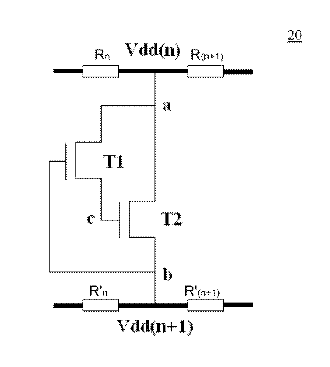
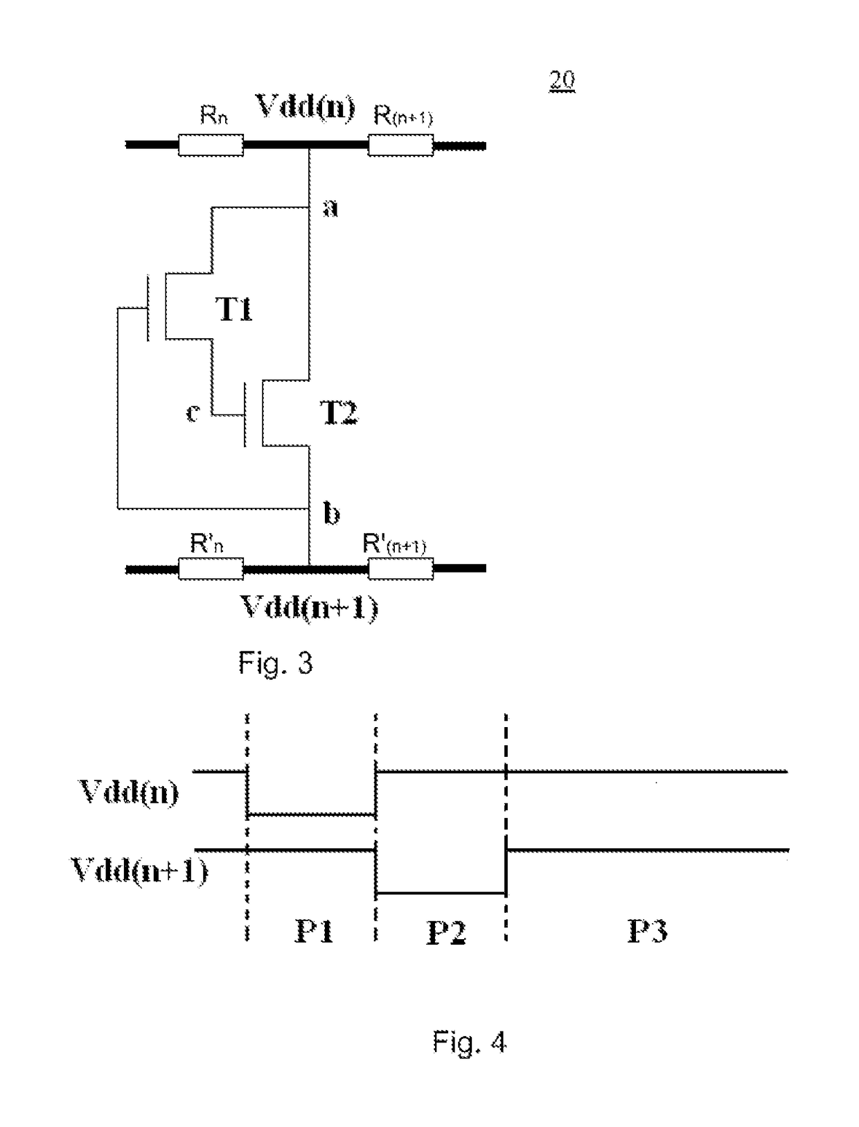
[0009]By means of the voltage driving pixel circuit of the present disclosure, two or more separately controlled thin film transistors are added in the pixels to form a switching circuit, and the routes of two adjacent power line voltages Vdd are connected, such that a network power line voltage of Vdd structure is formed in the light emitting phase, so as to avoid voltage change of the power line voltage Vdd of each row in the light emitting phase, thereby improving lateral resistance drop and crosstalk phenomenon of the variable power line voltage Vdd.
[0021]By means of the display panel and the method of driving the above voltage driving pixel circuit of the present disclosure, the voltage change of the power line voltage Vdd of each row in the light emitting phase is avoided, thereby improving lateral resistance drop and crosstalk phenomenon of the variable power line voltage Vdd.

Problems solved by technology

Therefore, it is urgently required in the prior art to improve the Mura phenomenon caused by resistance drop and the resulting crosstalk in image display.

Method used


Image

  • Voltage driving pixel circuit, display panel and driving method thereof
  • Voltage driving pixel circuit, display panel and driving method thereof
  • Voltage driving pixel circuit, display panel and driving method thereof

Examples


Embodiment Construction

[0027]It should be indicated firstly that the terms such as “up”, “down”, “left”, “right”, etc., regarding positions and directions mentioned in the present disclosure are directions viewed from the paper face of the drawings. Therefore, the terms such as “up”, “low”, “left”, “right”, etc., regarding positions and directions in the present disclosure only represent relative position relationships as shown in the drawings, this is only given for the purpose of explanations, not intended to limit the scope of this disclosure.

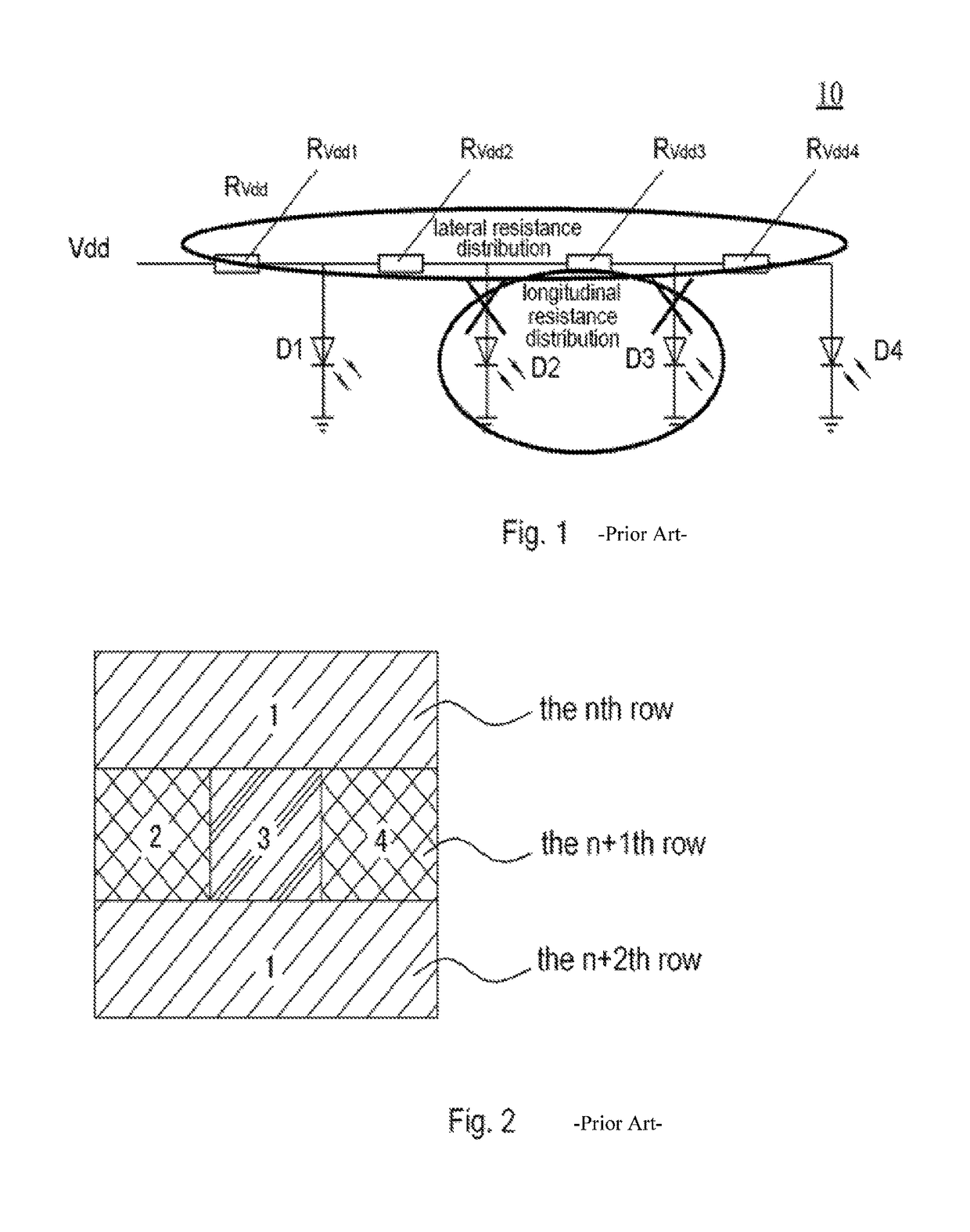
[0028]Next, the present disclosure will be described in detail with reference to FIGS. 1-4.

[0029]It has been described in detail in the BACKGROUND OF THE DISCLOSURE that due to the resistance drop generated by the lateral resistance distribution in two adjacent power lines in the prior art as shown in FIG. 1 and FIG. 2, the Mura as shown in area 3 is generated.

[0030]FIG. 3 schematically shows a voltage driving pixel circuit 20 in a pixel according to an embodiment...


PUM


Abstract

The present disclosure relates to a voltage driving pixel circuit, a display panel and a driving method thereof. The voltage driving pixel circuit comprises: any two power lines and a load connected in each power line, wherein there is one or more switching circuits between the any two power lines. By means of the voltage driving pixel circuit of the present disclosure, the power lines form a network structure in the light emitting phase, so as to avoid voltage change of the power line voltage Vdd of each row in the pixel in the light emitting phase, thereby improving lateral resistance drop and crosstalk phenomenon of the variable power line voltage Vdd.

Description

RELATED APPLICATION[0001]This disclosure claims the benefit of Chinese patent application of No. 201410633624.7 filed in the SIPO on Nov. 12, 2014, Chinese patent application of No. 201410633624.7 is incorporated herein by reference in its entirety.FIELD OF THE DISCLOSURE[0002]The present disclosure relates to a voltage driving pixel circuit, a display panel comprising the voltage driving pixel circuit as well as a driving method of the voltage driving pixel circuit.BACKGROUND OF THE DISCLOSURE[0003]In recent years, the organic light emitting diode (OLED) has become a very popular new flat panel display product at home and abroad, because the OLED display has the characteristics of self-luminous, wide viewing angle, short reaction time, high luminous efficiency, wide color gamut, low working voltage, thin panel, capable of fabricating large size and flexible panel as well as simple fabrication process etc., moreover, it also has the potential of low cost.[0004]In large size display ...

Claims


Application Information

Patent Timeline
Patent Type & Authority Patents(United States)
IPC IPC(8): G09G3/30G09G3/3216G09G3/3208
CPCG09G3/3216G09G2320/0223
Inventor YIN, JINGWENGAI, CUILI
Owner BOE TECH GRP CO LTD
Learn More