
LED structures for reduced non-radiative sidewall recombination

a technology of non-radiative sidewalls and led structures, applied in the field of micro leds, can solve problems such as low efficiency

Active Publication Date: 2018-01-09
APPLE INC
View PDF33 Cites 11 Cited by
  • Summary
  • Abstract
  • Description
  • Claims
  • Application Information

AI Technical Summary

Benefits of technology

Enhances radiative efficiency by reducing surface recombination and preserving the lattice structure, thereby increasing the luminous efficacy of micro LEDs, particularly at low current densities and pre-droop regions.

Problems solved by technology

At low current density the efficiency is low due to the strong effect of defects or other processes by which electrons and holes recombine without the generation of light, called non-radiative recombination.

Method used


Image

  • LED structures for reduced non-radiative sidewall recombination
  • LED structures for reduced non-radiative sidewall recombination
  • LED structures for reduced non-radiative sidewall recombination

Examples


Embodiment Construction

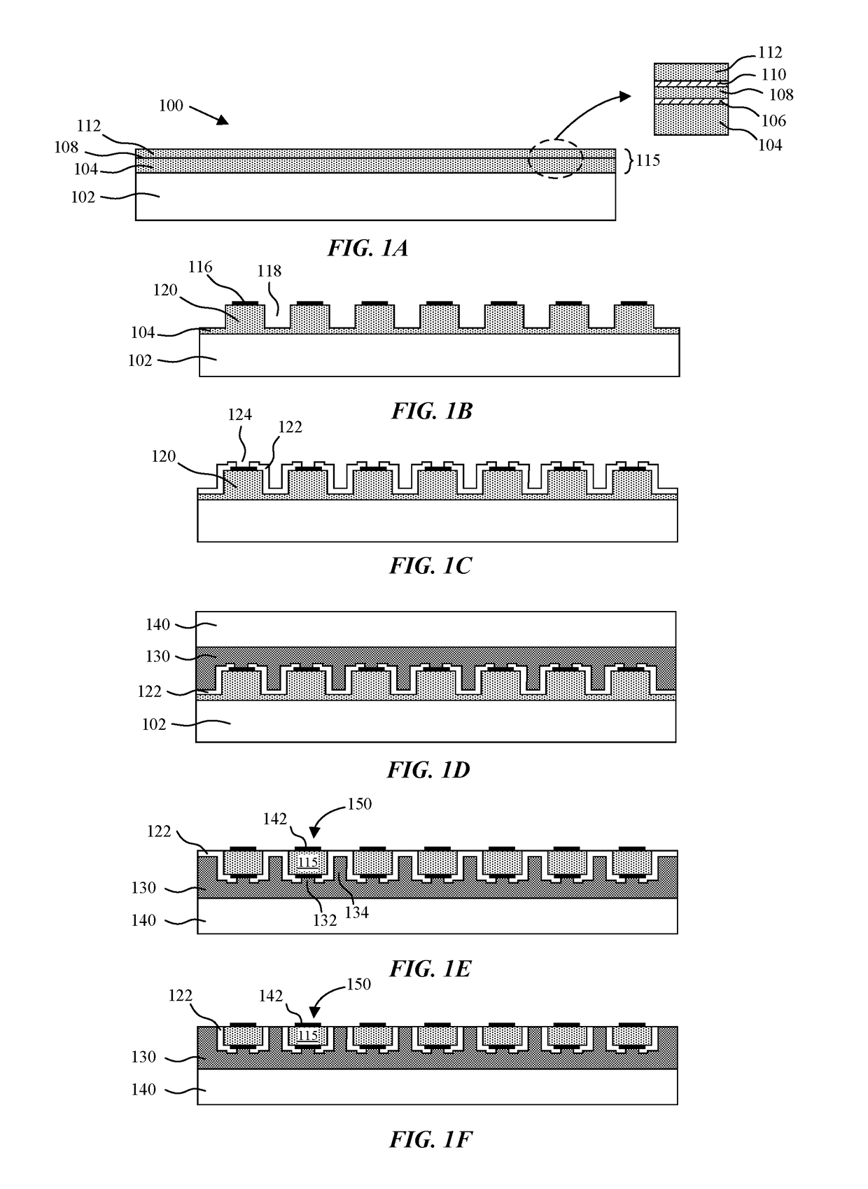
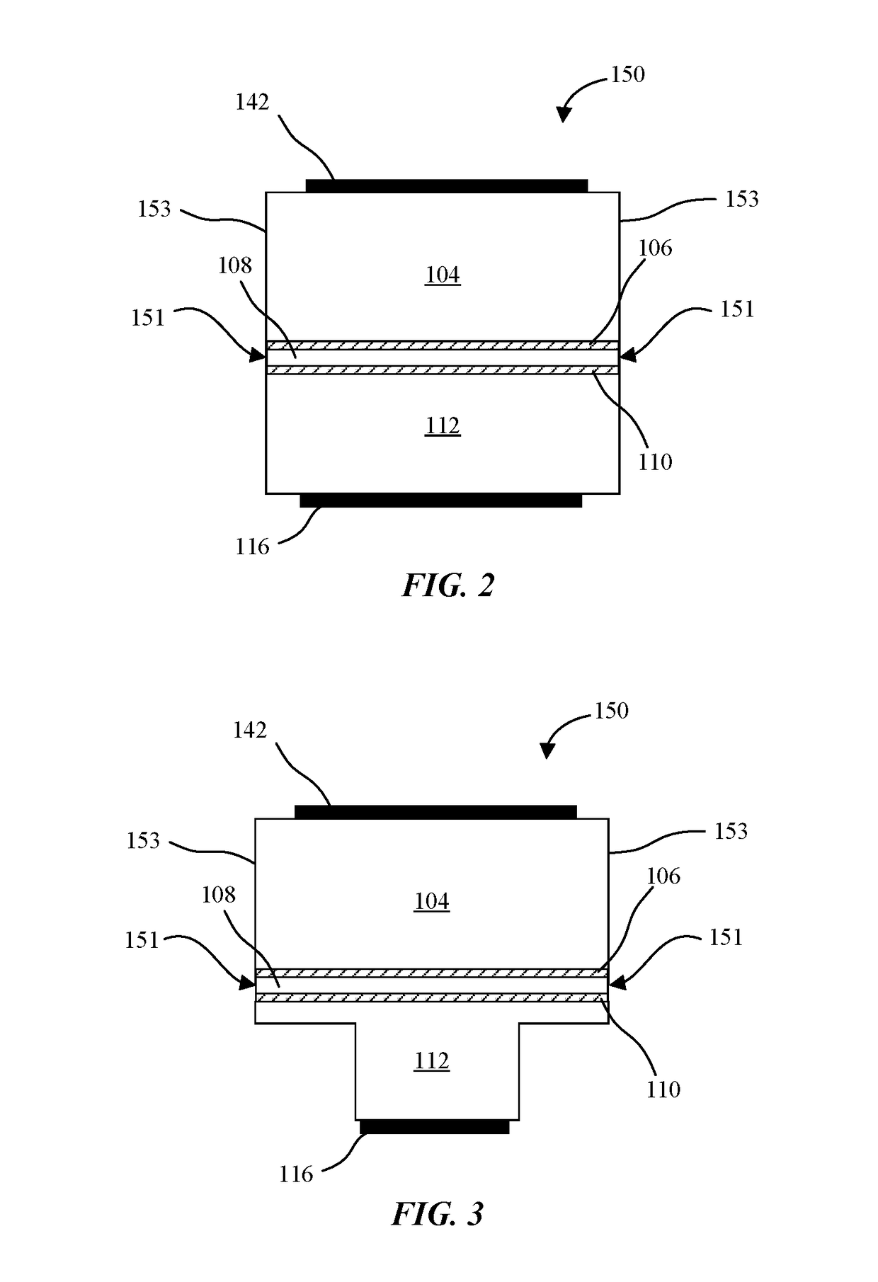
[0060]Embodiments describe LEDs and methods of forming LEDs with various structural configurations to mitigate non-radiative recombination at the LED sidewalls. For example, the various structures may include sidewall passivation techniques, current confinement techniques, and combinations thereof. However, certain embodiments may be practiced without one or more of these specific details, or in combination with other known methods and configurations. In the following description, numerous specific details are set forth, such as specific configurations, dimensions and processes, etc., in order to provide a thorough understanding of the embodiments. In other instances, well-known semiconductor processes and manufacturing techniques have not been described in particular detail in order to not unnecessarily obscure the embodiments. Reference throughout this specification to “one embodiment” means that a particular feature, structure, configuration, or characteristic described in connec...


PUM


Abstract

LED structures are disclosed to reduce non-radiative sidewall recombination along sidewalls of vertical LEDs including p-n diode sidewalls that span a top current spreading layer, bottom current spreading layer, and active layer between the top current spreading layer and bottom current spreading layer.

Description

RELATED APPLICATIONS[0001]This application is a continuation-in-part of co-pending U.S. patent application Ser. No. 15 / 199,803 filed Jun. 30, 2016, which is a continuation-in-part of U.S. patent application Ser. No. 14 / 853,614 filed Sep. 14, 2015, now issued as U.S. Pat. No. 9,484,492, and claims the benefit of priority from U.S. Provisional Application No. 62 / 100,348 filed Jan. 6, 2015, the full disclosures of which are incorporated herein by reference.BACKGROUND[0002]Field[0003]Embodiments described herein relate LEDs. More particularly, embodiments relate to micro LEDs.[0004]Background Information[0005]Light emitting diodes (LEDs) are increasingly being considered as a replacement technology for existing light sources. For example, LEDs are found in signage, traffic signals, automotive tail lights, mobile electronics displays, and televisions. Various benefits of LEDs compared to traditional lighting sources may include increased efficiency, longer lifespan, variable emission spe...

Claims


Application Information

Patent Timeline
Patent Type & Authority Patents(United States)
IPC IPC(8): H01L29/06H01L31/00H01L33/06H01L33/00H01L33/30H01L33/44
CPCH01L33/06H01L33/0008H01L33/44H01L33/0062H01L33/305H01L33/0025H01L33/145H01L33/20H01L33/24H01L33/56
Inventor BOUR, DAVID P.MCGRODDY, KELLYHAEGER, DANIEL ARTHURPERKINS, JAMES MICHAELCHAKRABORTY, ARPANDROLET, JEAN-JACQUES P.SIZOV, DMITRY S.
Owner APPLE INC
Learn More