
Autonomous laser-powered vehicle

a laser-powered vehicle and autonomous technology, applied in the field of field-deployed autonomous cryobots, can solve the problems of inability to cast with the very complex internal channels that are required, the complexity of the necessary piping, and the inability to meet the requirements of large-scale billet sizes

Active Publication Date: 2017-12-26
STONE AEROSPACE INC
View PDF81 Cites 5 Cited by
  • Summary
  • Abstract
  • Description
  • Claims
  • Application Information

AI Technical Summary

Benefits of technology

The present invention is a laser-powered vehicle designed to penetrate deep ice caps on both Earth and space. It is designed to melt a path in front of the vehicle as it descends. The vehicle has a cylindrical configuration and is made up of rods and modular panels that can be easily removed for access. The vehicle includes beam optics, a beam expansion cavity, a beam dump heat exchanger, an antenna, a pump assembly, an onboard computer stack, an end plate, and an onboard bare fiber spooler. The vehicle can use an armored process fiber to connect the melt head optics to the beam dump. The technical effect of this invention is to provide a powerful and efficient vehicle for deep ice cap penetration.

Problems solved by technology

However, with regard to beryllium oxide (BeO), toxicity issues and the complexity of the necessary piping precluded this option in the end on the grounds of fabrication problems.
Concerning copper as material for the beam dump, it was not available in large billet sizes and similarly could not be cast with the very complex internal channels that are required.

Method used


Image

  • Autonomous laser-powered vehicle
  • Autonomous laser-powered vehicle
  • Autonomous laser-powered vehicle

Examples


Embodiment Construction

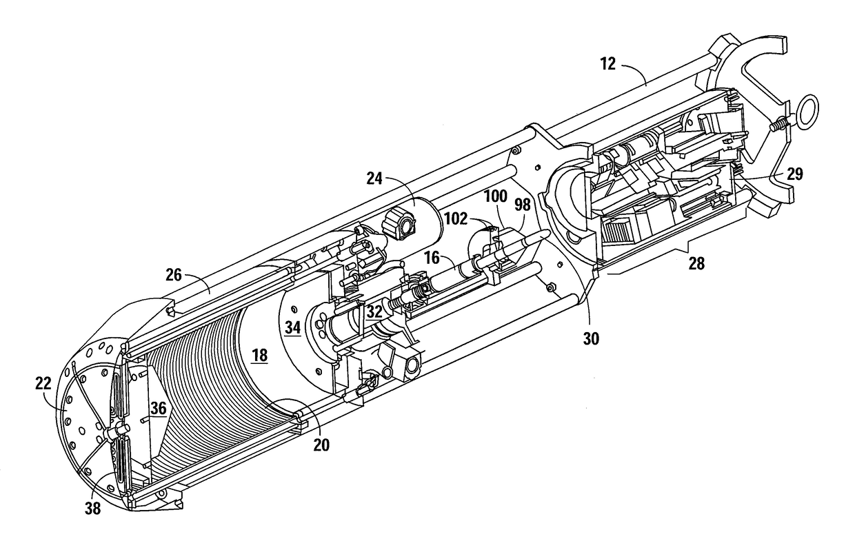
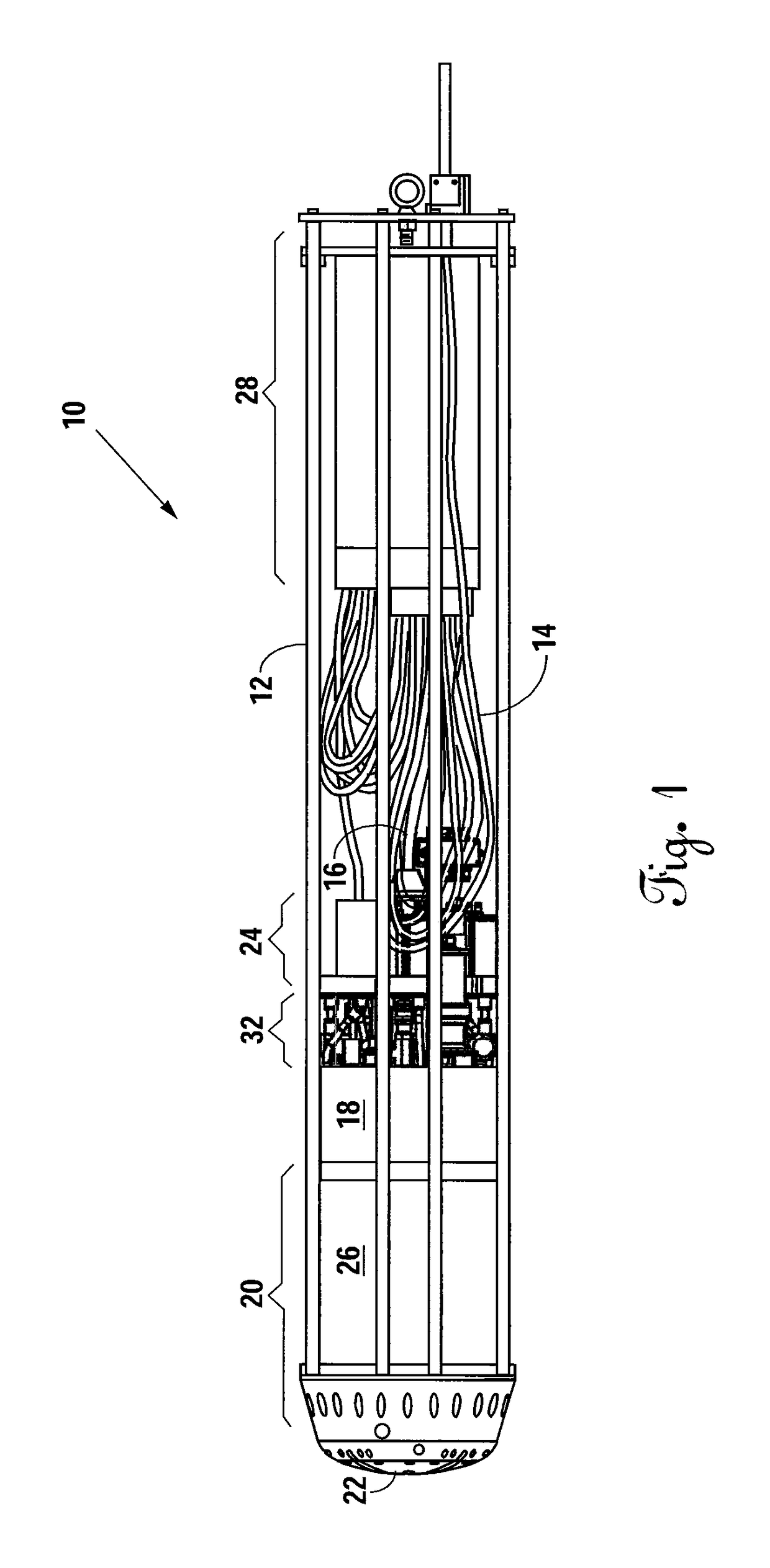
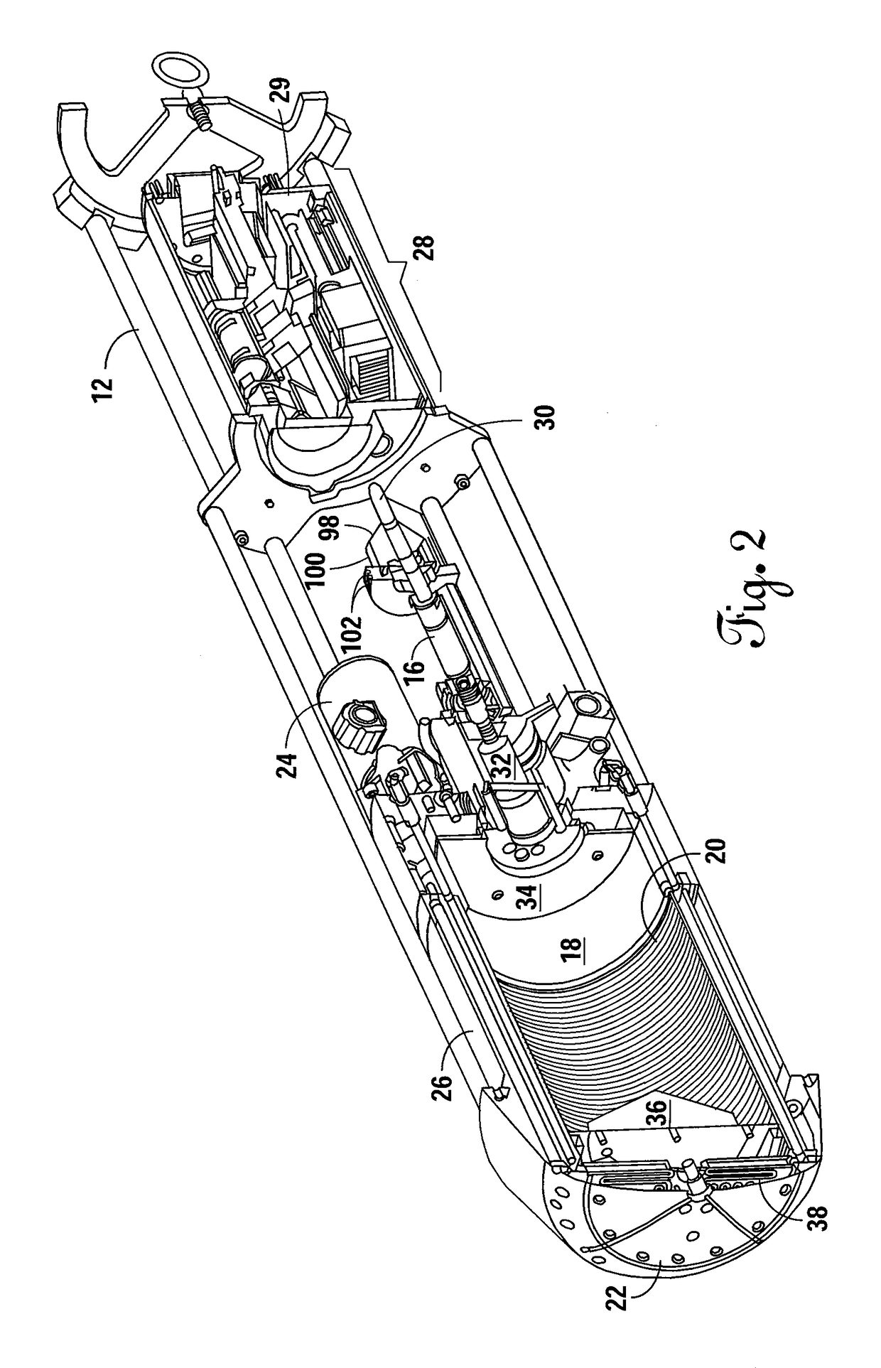
[0030]FIG. 1 depicts the present invention, or vehicle 10, with the modular exterior shell panels removed. The vehicle exterior structure is comprised of a plurality of rods 12 and a plurality of modular exterior shell panels (not shown). The plurality of rods 12 serves as a skeleton or structural anchor for the plurality of panels. The panels can be removed for access to any portion of the vehicle 10. When the vehicle 10 is fully assembled, the plurality of panels provides a smooth exterior surface of the vehicle 10. A prototype vehicle 10 designed to function with a 5 kilowatt laser measures 25.4 cm in diameter×1.25 m in length. There is no “optimum” size for this vehicle. The 25.4 cm diameter provides a reasonable rate of descent through ice with the size of laser used. It is highly likely that a vehicle with a larger diameter in conjunction with much larger lasers can be used for a Europa full-mission simulation mission in Antarctica. For example, up to a 200 kilowatt laser may ...


PUM


Abstract

An autonomous laser-powered vehicle designed to autonomously penetrate through ice caps of substantial (e.g., kilometers) thickness by melting a path ahead of the vehicle as it descends. A high powered laser beam is transmitted to the vehicle via an onboard bare fiber spooler. After the beam enters through the dispersion optics, the beam expands into a cavity. A radiation shield limits backscatter radiation from heating the optics. The expanded beam enters the heat exchanger and is reflected by a dispersion mirror. Forward-facing beveled circular grooves absorb the reflected radiant energy preventing the energy from being reflected back towards the optics. Microchannels along the inner circumference of the beam dump heat exchanger maximize heat transfer. Sufficient amount of fiber is wound on the fiber spooler to permit not only a descent but also to permit a sample return mission by inverting the vehicle and melting its way back to the surface.

Description

CROSS REFERENCE TO RELATED APPLICATIONS[0001]This original non-provisional application claims priority to and the benefit of U.S. provisional application Ser. No. 61 / 879,356, filed Sep. 18, 2013, and entitled “Autonomous Laser-Powered Vehicle,” which is incorporated by reference herein.[0002]U.S. application Ser. No. 14 / 292,495, filed May 30, 2014, and entitled “Power Conversion Module for Use with Optical Energy Transfer and Conversion System,” is incorporated by reference herein.[0003]U.S. application Ser. No. 13 / 303,449, filed Nov. 23, 2011 and entitled “Optical Energy Transfer and Conversion System,” is incorporated by reference herein.STATEMENT REGARDING FEDERALLY SPONSORED RESEARCH OR DEVELOPMENT[0004]This invention was made with Government support under Grant No. NNX11AJ89G awarded by NASA. The Government has certain rights in this invention.BACKGROUND OF THE INVENTION[0005]1. Field of the Invention[0006]The present invention relates to autonomous laser-powered vehicles. More...

Claims


Application Information

Patent Timeline
Patent Type & Authority Patents(United States)
IPC IPC(8): G02B6/00G02B7/00G02B19/00E21B7/00E21B7/15
CPCE21B7/008E21B7/15G02B19/0047G02B19/0028G02B7/008G02B23/2492G02B6/3624B64G99/00B64G1/00G02B6/50
Inventor STONE, WILLIAM C.HOGAN, BARTHOLOMEW P.
Owner STONE AEROSPACE INC
Learn More