Device, system and method for skin detection

a technology of skin detection and device, applied in the field of devices, system and methods for skin detection, can solve the problems of not being robust to changes in ambient light color, not being able to detect skin areas under low illumination conditions or in darkness, and achieving the effect of simple but effective and efficien

Active Publication Date: 2017-12-12
KONINKLJIJKE PHILIPS NV
View PDF15 Cites 4 Cited by
  • Summary
  • Abstract
  • Description
  • Claims
  • Application Information

AI Technical Summary

Benefits of technology

[0015]It is an object of the present invention to provide a device and a corresponding method as well as a system which allow a reliable, accurate and fast detection of skin.
[0027]The present invention solves the problems and disadvantages of the known methods and devices using a three step approach. First, in the analysis window (time-interval) an image (mostly the first of the window) is segmented. Next, individual segments are tracked over time (resulting in tracked segments over time which each may also be considered as a volume). Said tracking is performed by use of one or more features, including features describing the temporal domain, which e.g. have been extracted from the tracked segments (volumes). Finally, a clustering is performed of said tracked segments based on said features identifying one or more clusters that contain living tissue, i.e. skin area, and possibly one or more clusters that do not contain any living tissue. This allows a reliable, accurate and fast detection of skin in a sequence of image frames as typically acquired by a video camera.
[0030]In another embodiment said clustering unit is configured to use temporal color variations of the tracked segments as feature for clustering the tracked segments. For instance, said clustering unit may be configured to perform a Fourier transformation of the spatially combined color value of at least part of the pixels in a tracked segment and to cluster two tracked segments into a single cluster if their amplitude peak frequency has substantially the same value and phase. Hence, to know if two tracked segments belong to the same cluster (i.e. to living being) the frequency and the phase of their temporal color variations may be compared. This provides for a rather simple but efficient way of clustering.
[0031]In another embodiment said clustering unit is configured to compute the inner product between normalized time signals of different tracked segments and to cluster said tracked segments into a single cluster if said inner product exceeds a predetermined threshold. Said time signals are preferably color signals in a time window, which may be normalized by their mean in that window. The higher the value of the inner product is, the more similar the tracked segments are. This provides for another rather simple but effective way of clustering.

Problems solved by technology

Therefore, remote photoplethysmographic systems and devices are considered unobtrusive and well suited for medical as well as non-medical everyday applications.
However, they are not robust to changes of ambient light color, which will change the color of light reflected from a skin area, and are not able to detect skin areas under low illumination conditions or in darkness.
Moreover, such methods cannot always differentiate a skin from other objects with the same color.
However, the reliability of the approach depends on the robustness of PPG signal extractions, thus it is impacted by motion of a subject and the blood perfusion level.
Therefore, if a pulse signal is not periodic or is weak, a camera-based system will have difficulties to detect the segment the skin areas.
Moreover, the approach is also computationally expensive.
A problem with surveillance camera images is that it is difficult to distinguish between a face and a mask or a picture of a face.
A problem with camera-based vital signs monitoring is that the vital signs can only be extracted from living tissue, usually some skin-area, but currently this area is most often manually selected from the video and consequently tracked, or one has to rely on a face detector that typically fails on side views of a face, and certainly does not give anything useful for non-facial skin in the video.

Method used


Image

  • Device, system and method for skin detection
  • Device, system and method for skin detection
  • Device, system and method for skin detection

Examples


Embodiment Construction

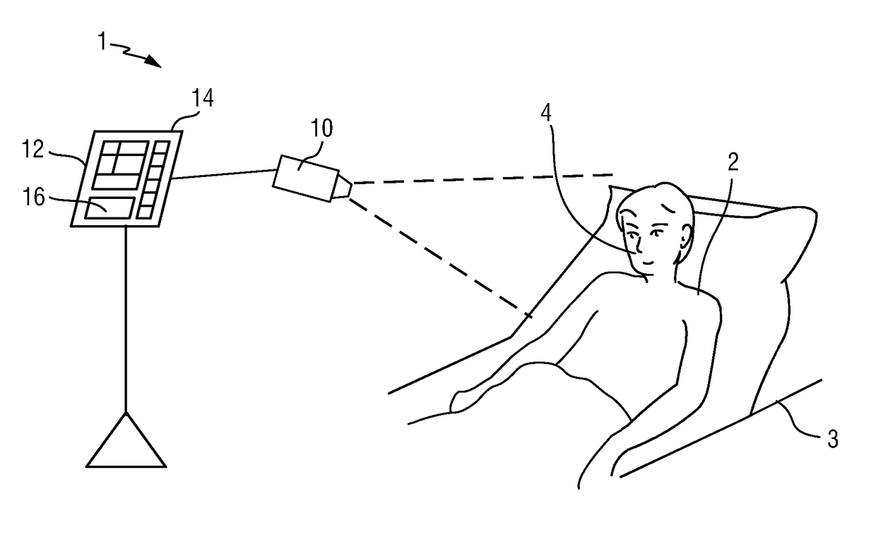
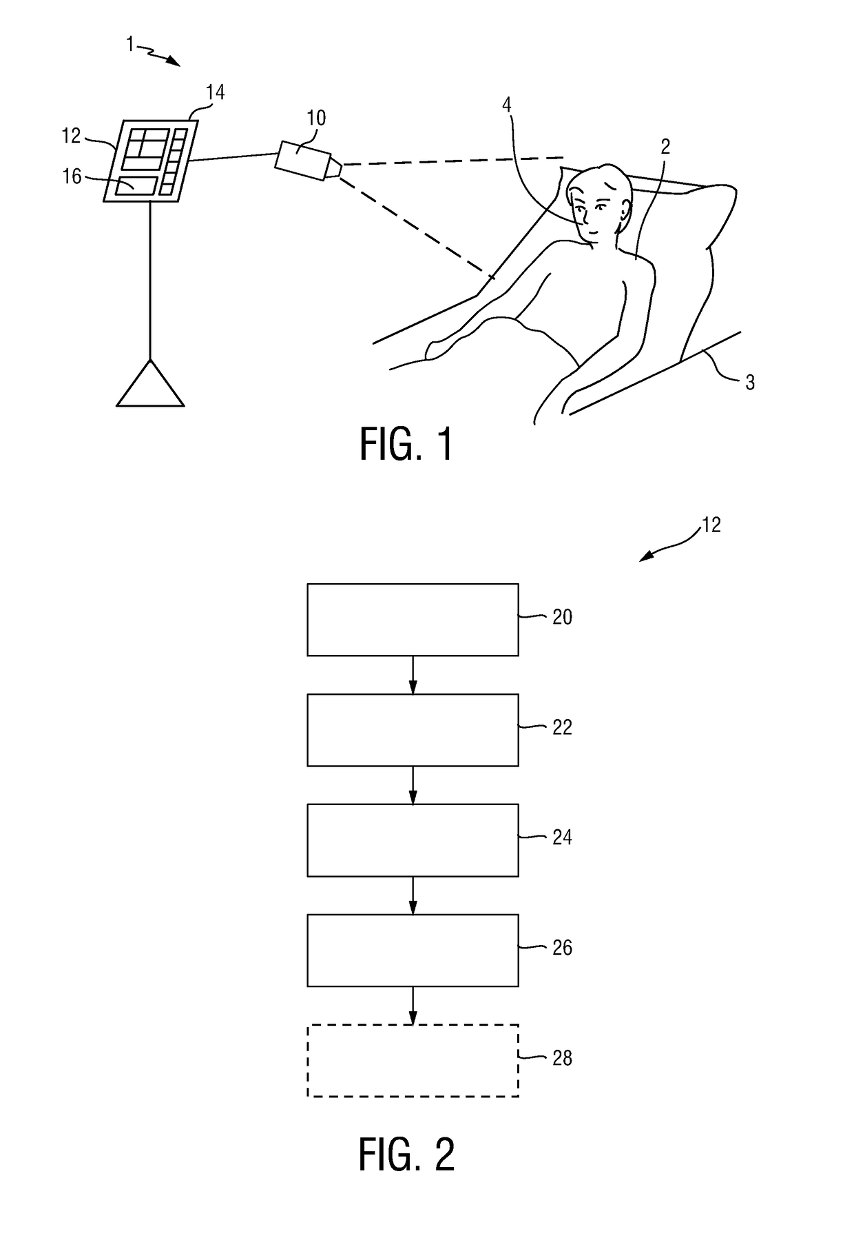
[0062]FIG. 1 shows a schematic diagram of a first embodiment of a system 1 for skin detection according to the present invention. The system 1 comprises an imaging unit 10 for acquiring a sequence of image frames of a scene over time. The scene includes, in this example, a patient 2 lying in a bed 3, e.g. in a hospital room or other healthcare facility, but may also be the environment of a neonate or premature infant, e.g. lying in an incubator / warmer, or a person at home or in a different environment. The imaging unit 10 is particularly a camera (also referred to as detection unit or as camera-based or remote PPG sensor), which is configured to obtain images of the scene, preferably including skin areas 4 of the patient 2. In an application of the device for obtaining vital signs of the patient 2, the skin area 4 is preferably an area of the face, such as the cheeks or the forehead, but may also be another area of the body, such as the hands or the arms.

[0063]The image frames captu...


PUM


Abstract

An input unit (20) obtains a sequence of image frames over time. A segmentation unit (22) segments image frames of the sequence of image frames. A tracking unit (24) tracks segments of the segmented image frame over time in the sequence of image frames. A clustering unit (26) clusters the tracked segments to obtain clusters representing skin of a subject by use of one or more image features of the tracked segments.

Description

CROSS-REFERENCE TO PRIOR APPLICATION[0001]This application claims the benefit of European Patent Application No. 14197951.8 filed Dec. 15, 2014. The application is hereby incorporated by reference herein.FIELD OF THE INVENTION[0002]The present invention relates to a device, system and method for skin detection.BACKGROUND OF THE INVENTION[0003]Vital signs of a person, for example the heart rate (HR), the respiration rate (RR) or the arterial blood oxygen saturation (SpO2), serve as indicators of the current health state of a person and as powerful predictors of serious medical events. For this reason, vital signs are extensively monitored in inpatient and outpatient care settings, at home or in further health, leisure and fitness settings.[0004]One way of measuring vital signs is plethysmography. Plethysmography generally refers to the measurement of volume changes of an organ or a body part and in particular to the detection of volume changes due to a cardio-vascular pulse wave trav...

Claims


Application Information

Patent Timeline
Patent Type & Authority Patents(United States)
IPC IPC(8): G06K9/00G06T7/00G06K9/62G06K9/46G06T7/13G06T7/246G06T7/90A61B5/024A61B5/00A61B5/1455G06K9/52G06V10/56G06V10/44
CPCG06T7/0012G06K9/00496G06K9/4604G06K9/4652G06K9/6218G06K9/6224G06T7/246G06T7/90G06T7/13G06K9/522A61B5/02416A61B5/14551A61B5/4887G06V10/56G06V10/431G06V10/7635G06V40/15G06V10/44G06F18/23G06F18/2323G06F2218/00
Inventor DE HAAN, GERARD
Owner KONINKLJIJKE PHILIPS NV
Why Eureka
Try Eureka