Display control device, projection device, and non-transitory storage medium
a control device and projection device technology, applied in the direction of picture reproducers using projection devices, static indicating devices, instruments, etc., to achieve the effect of improving the visibility of the imag
- Summary
- Abstract
- Description
- Claims
- Application Information
AI Technical Summary
Benefits of technology
Problems solved by technology
Method used
Image
Examples
first embodiment
(First Embodiment)
[0029]A first embodiment of the present disclosure will be described with reference to FIGS. 1 to 11.
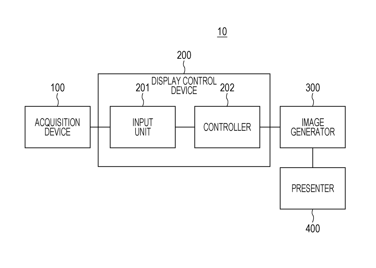
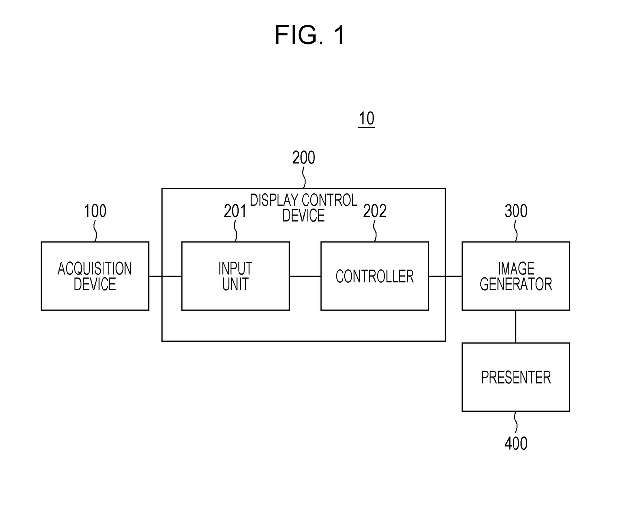
[0030]First, a configuration example of a display system 10 according to the embodiment will be described with reference to FIG. 1. FIG. 1 is a block diagram showing the configuration example of the display system 10 according to the embodiment.
[0031]The display system 10 is used in a moving object such as a vehicle, for example. Specifically, the display system 10 may either be an in-vehicle apparatus or an apparatus brought into the vehicle. Note that although the embodiment will be described with an example of a case where the display system 10 is applied to the vehicle, the moving object is not limited to the vehicle and may be a vessel, an aircraft, or the like. In addition, although the embodiment will be described with an example of a case where the user is an occupant (a driver or a passenger, for example) of the vehicle, it is not limited thereto.
[0032]In F...
first modification
(First Modification)
[0101]In the first embodiment, when setting the hue with the decreased blue component, the controller 202 may set the hue depending on the luminance of the display medium. A specific example of this case will be described with reference to FIG. 4. FIG. 4 is a diagram showing an example of a table used for setting the hue.
[0102]In the table shown in FIG. 4, the luminance of the display medium and a hue change amount are registered in association with each other. Note that “default setting” shown in FIG. 4 means that, for example, the hue change amount is zero. The table in FIG. 4 is stored in the predetermined storage, for example.
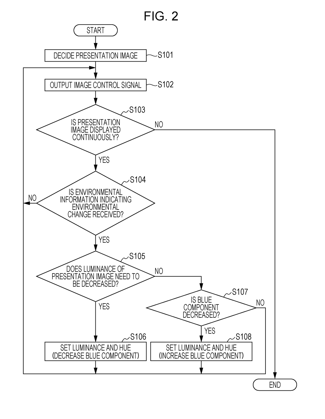
[0103]First, for example, when setting the hue with the decreased blue component in the processing in step S106 in FIG. 2, the controller 202 reads the table in FIG. 4 and the information on the color wheel in FIG. 3 from the predetermined storage. Next, the controller 202 decides the hue change amount corresponding to the currently-set ...
second modification
(Second Modification)
[0106]The first embodiment has been described with the example of the case where the information indicating the in-vehicle illuminance is used as the example of the environmental information. However, in addition to the in-vehicle illuminance, illuminance in front of the vehicle (hereinafter, referred to as front illuminance) may also be used as an example of the environmental information. A specific example of this case will be described below.
[0107]A configuration of the modification is identical to the configuration shown in FIG. 1, except that the acquisition device 100 is provided inside the vehicle and includes the illuminance sensor (the example of the first sensor) that measures the in-vehicle illuminance and an illuminance sensor (an example of a second sensor) that recognizes the front illuminance. Thus, in the modification, the acquisition device 100 outputs the information indicating the in-vehicle illuminance and the information indicating the front...
PUM
 Abstract
Description
Claims
Application Information
 - R&D
- Intellectual Property
- Life Sciences
- Materials
- Tech Scout
- Unparalleled Data Quality
- Higher Quality Content
- 60% Fewer Hallucinations
Browse by: Latest US Patents, China's latest patents, Technical Efficacy Thesaurus, Application Domain, Technology Topic, Popular Technical Reports.
© 2025 PatSnap. All rights reserved.Legal|Privacy policy|Modern Slavery Act Transparency Statement|Sitemap|About US| Contact US: help@patsnap.com


