
Initiator head assembly

a technology of initiator and head assembly, which is applied in the direction of fluid removal, borehole/well accessories, weapons, etc., can solve the problems of inadvertent disconnect of wires, difficulty in passing such wires through the initiator, and difficulty in maintaining a pressure differential across the components

Active Publication Date: 2017-11-21
DYNAENERGETICS
View PDF17 Cites 44 Cited by
  • Summary
  • Abstract
  • Description
  • Claims
  • Application Information

AI Technical Summary

Benefits of technology

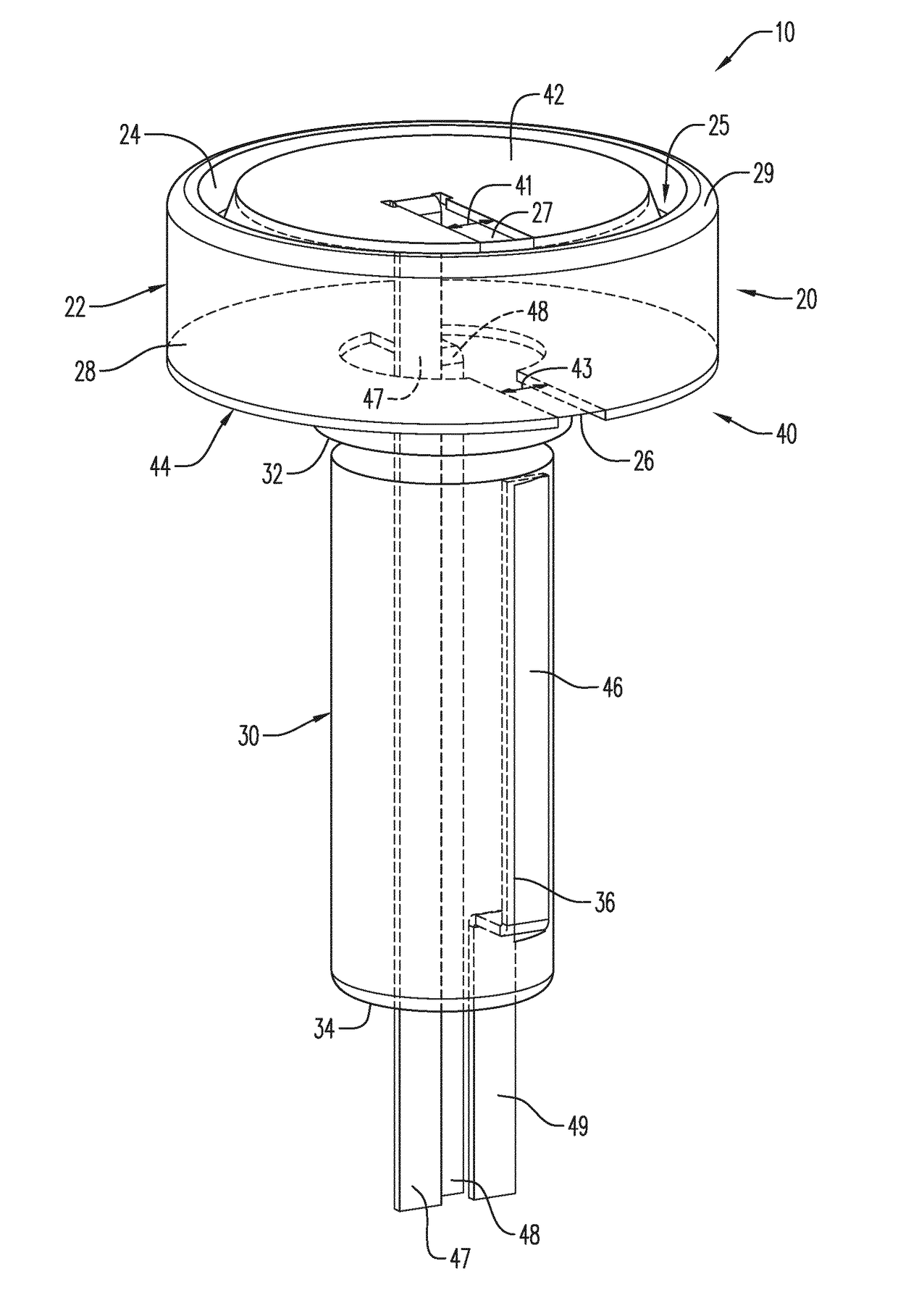
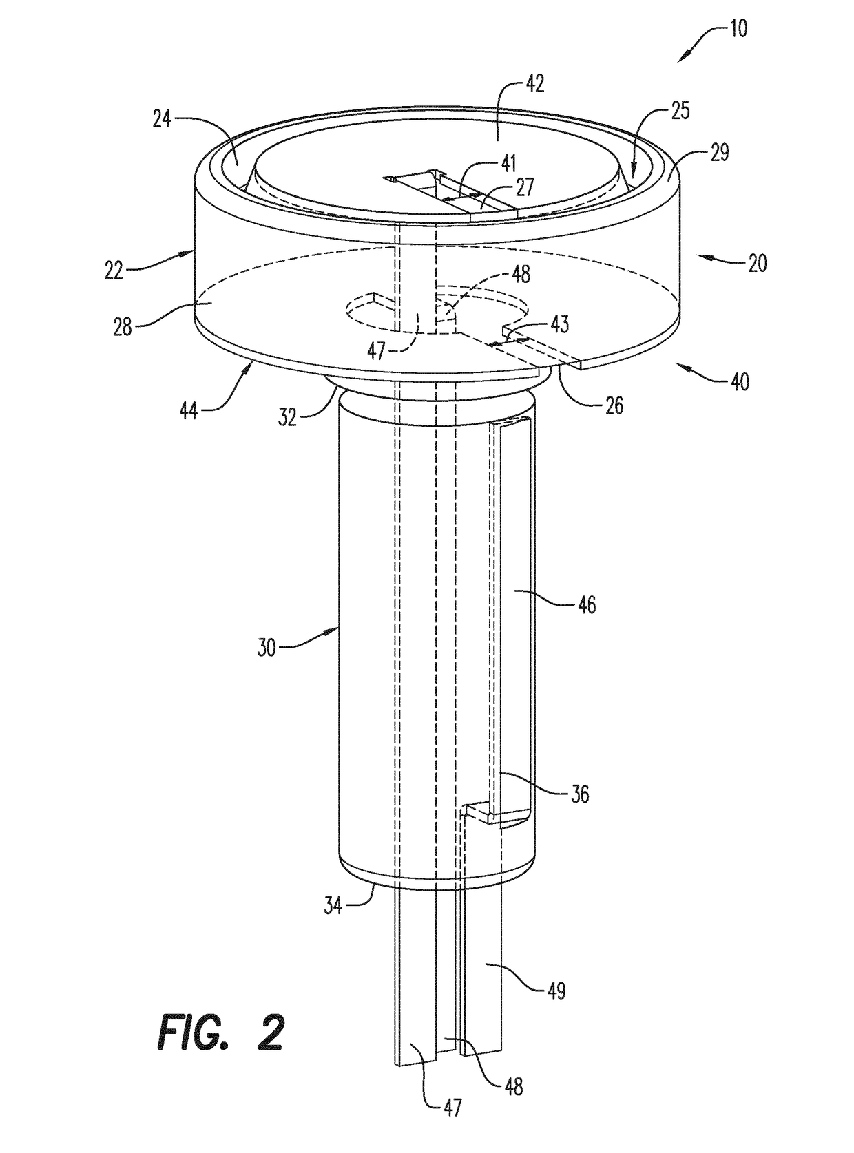
The patent describes an initiator head assembly used in a downhole tool. The assembly has a body with an embedded electrical contact component which maintains a higher pressure at one end of the body. The body is formed as a unitary component. The technical effects of this design include improved sealing against pressure leakage and better efficiency in controlling the pressure at the desired location in the downhole tool.

Problems solved by technology

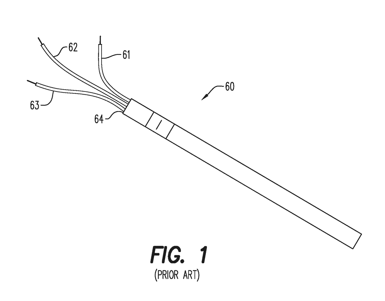
Passage of such wires through the initiator, while maintaining a pressure differential across the component, has proved challenging.
Since the electrical wire must extend through much of the perforating gun assembly, it is easily twisted and crimped during assembly.
In addition, when a wired detonator is used it must be manually connected to the electrical wire, which has lead to multiple problems.
Due to the rotating assembly of parts, the wires can become torn, twisted and / or crimped / nicked, the wires may be inadvertently disconnected, or even mis-connected in error during assembly, not to mention the safety issues associated with physically and manually wiring live explosives.

Method used


Image

  • Initiator head assembly
  • Initiator head assembly
  • Initiator head assembly

Examples


Embodiment Construction

[0027]Reference will now be made in detail to various embodiments. Each example is provided by way of explanation, and is not meant as a limitation and does not constitute a definition of all possible embodiments.

[0028]In an embodiment, the assembly provides an improved apparatus for use with a wireless connection—that is, without the need to attach, crimp, cut or otherwise physically and manually connect external wires to the component. Rather, the connections are made wirelessly, by simply abutting, for instance, electrically contactable components, of which at least a portion thereof is positioned proximal to an external surface of the pressure barrier. As used herein, the term “proximal” means on or near or next to or nearest or even embedded within. For the sake of clarity, the term “wireless” does not refer to a WiFi connection, but rather to this notion of being able to transmit electrical signals through the electrical componentry without connecting external wires to the com...


PUM


Abstract

According to an aspect an initiator head assembly (10, 110) is provided having particular application with a perforating gun assembly, in particular for oil well drilling applications. The initiator head assembly includes a body (20, 120) and an electrical contact component (40, 140) with the electrical contact component embedded therein. In another aspect, the initiator head assembly with the embedded electrical contact component is configured as a unitary component and also to hold a pressure differential across the top and bottom parts of the initiator head assembly. In an aspect, the method of forming the initiator head assembly is also generally described.

Description

CROSS-REFERENCE TO RELATED APPLICATIONS[0001]This application claims priority to PCT Application No. PCT / EP2015 / 0059381 filed Apr. 29, 2015, which claims the benefit of U.S. Provisional Application No. 61 / 988,722, filed May 5, 2014, and U.S. Provisional Application No. 62 / 050,678, filed Sep. 15, 2014, all of which are incorporated herein by reference in their entireties.FIELD[0002]Described generally herein is an initiator head assembly having an embedded electric feed-through for use with a perforating gun assembly, in particular for oil well drilling applications.BACKGROUND[0003]In exploration and extraction of hydrocarbons, such as fossil fuels (e.g. oil) and natural gas, from underground wellbores extending deeply below the surface, various downhole tools are inserted below the ground surface and include sometimes complex machinery and explosive devices. Examples of the types of equipment useful in exploration and extraction, in particular for oil well drilling applications, inc...

Claims


Application Information

Patent Timeline
Patent Type & Authority Patents(United States)
IPC IPC(8): F42B3/10E21B43/1185F42C19/06F42B3/26F42D1/04F42D1/045F42B3/103
CPCE21B43/1185F42B3/103F42B3/26F42D1/045F42D1/041F42D1/043F42C19/06
Inventor EITSCHBERGER, CHRISTIAN
Owner DYNAENERGETICS
Learn More