
Servo and robot with servo

a technology of servo and robot, which is applied in the field of robots, can solve the problems of unstable output shaft or steering box, easy damage to the servo, and reduced strength, and achieve the effects of improving strength, compact structure, and large single-stage transmission ratio

Active Publication Date: 2017-11-14
UBTECH ROBOTICS CORP LTD
View PDF6 Cites 20 Cited by
  • Summary
  • Abstract
  • Description
  • Claims
  • Application Information

AI Technical Summary

Benefits of technology

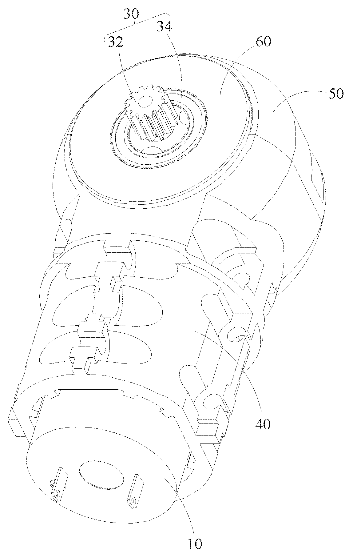
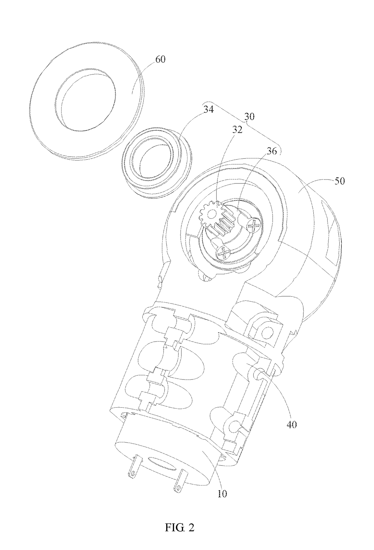
The present invention provides a servo with a compact structure and a larger single stage transmission ratio through the first-stage and second-stage deceleration mechanisms. The servo could directly connect with an exterior component through the external spline output shaft, reducing friction and increasing lifetime. The external spline output shaft is used as the second output shaft for increased deceleration effects. The power output mechanism is fixed by adding one stage of bearing to the exterior of the servo through disposing the output bearing on the power output mechanism. The bearing could be used alone with an internal spline or an external spline to strengthen the structure of the servo and increase the precision of the angle outputted by the power output mechanism.

Problems solved by technology

As a result, the internal splines are often worn, hence the strength is reduced and is easy to be destroyed.
In addition, it's not easy to be connected to an external gear so as to increase more deceleration effects.
Furthermore, the original servo is without one more stage of bearing, which causes the instability of the output shaft or the steering box.
Since it's liable to vibrate, the precision of the output angle is affected.
The purpose of the present disclosure is providing a servo to resolve the technical problems including the weakness in the strength of existed servos and is liable to cause structural destruction which happens when outputting torque and instability.

Method used


Image

  • Servo and robot with servo
  • Servo and robot with servo
  • Servo and robot with servo

Examples


Embodiment Construction

[0025]The disclosure is illustrated by way of example and not by way of limitation in the figures of the accompanying drawings, in which like reference numerals indicate similar elements. It should be noted that references to “an” or “one” embodiment in this disclosure are not necessarily to the same embodiment, and such references can mean “at least one” embodiment.

[0026]In the descriptions of the present disclosure, what need to be comprehended is that, the direct or location relationships indicated by the terms “length”, “width”, “upper”, “lower”, “front”, “back”, “left”, “right”, “vertical”, “horizontal”, “top”, “bottom”, “interior”, “exterior” and the like are based on the orientation or positional relation shown in the drawings, which are merely for the convenience to describe the present disclosure and for simplifying the descriptions, rather than indicating or implying the descripted apparatus or component need to have a particular orientation and constructed / operated in the...


PUM


Abstract

A servo and a robot with the servo are provided. The servo comprises a power input apparatus with a first output shaft, a deceleration apparatus, and a power output mechanism. The deceleration apparatus comprises a first-stage deceleration mechanism and a second-stage deceleration mechanism. The power output mechanism comprises a second output shaft and an output bearing fixedly installed on the second output shaft, wherein the second output shaft is an external spline output shaft. Through the external spline output shaft and the output bearing disposed on the power output mechanism, the servo could directly connect with an exterior component through the external spline output shaft, and the strength is improved. As a result, the friction between the servo and the exterior component is reduced, and the lifetime is therefore increased.

Description

CROSS REFERENCE TO RELATED APPLICATIONS[0001]This application claims priority to Chinese Patent Application No. 201611101436.5, filed Dec. 5, 2016, which is hereby incorporated by reference herein as if set forth in its entirety.BACKGROUND1. Technical Field[0002]The present disclosure generally relates to robots, and particularly to a servo and a robot with the servo.2. Description of Related Art[0003]A servo comprises a motor, a gear set driven to rotate by the motor, and a power output shaft for outputting power which is connected with the gear set, and a steering box connecting the power output shaft and an exterior connection part.[0004]In the existed techniques, a plurality of internal splines are formed between the steering wheel and the power output shaft, which are for connecting an external connection component so as to rotate. However, the power output shaft is disposed inside the steering box, which is connected to an external component through the internal splines, and t...

Claims


Application Information

Patent Timeline
Patent Type & Authority Patents(United States)
IPC IPC(8): F16H57/08B25J9/12F16H1/20F16H1/28F16H37/04
CPCB25J9/126B25J9/102F16H1/203F16H1/28F16H37/041B25J17/00B25J19/00B25J9/108
Inventor DU, XUCHAOLIU, LEFENGDING, HONGYUSHU, WENQUANXIONG, YOUJUN
Owner UBTECH ROBOTICS CORP LTD
Learn More