
Means and devices to collect water vapors

a technology of water vapor and water vapor, which is applied in the direction of evaporation, evaporating devices, separation processes, etc., can solve the problems of large energy and equipment required in the process, slow and relatively inefficient processes, and produce relatively expensive fresh water. , to achieve the effect of increasing the condensation rate of water vapor

Inactive Publication Date: 2017-11-07
HSIA CHIH YU +2
View PDF2 Cites 2 Cited by
  • Summary
  • Abstract
  • Description
  • Claims
  • Application Information

AI Technical Summary

Problems solved by technology

However, these processes require substantial energy and equipment.
They produce relatively costly fresh waters.
However, these processes are slow and relatively inefficient.

Method used


Image

  • Means and devices to collect water vapors
  • Means and devices to collect water vapors
  • Means and devices to collect water vapors

Examples


Embodiment Construction

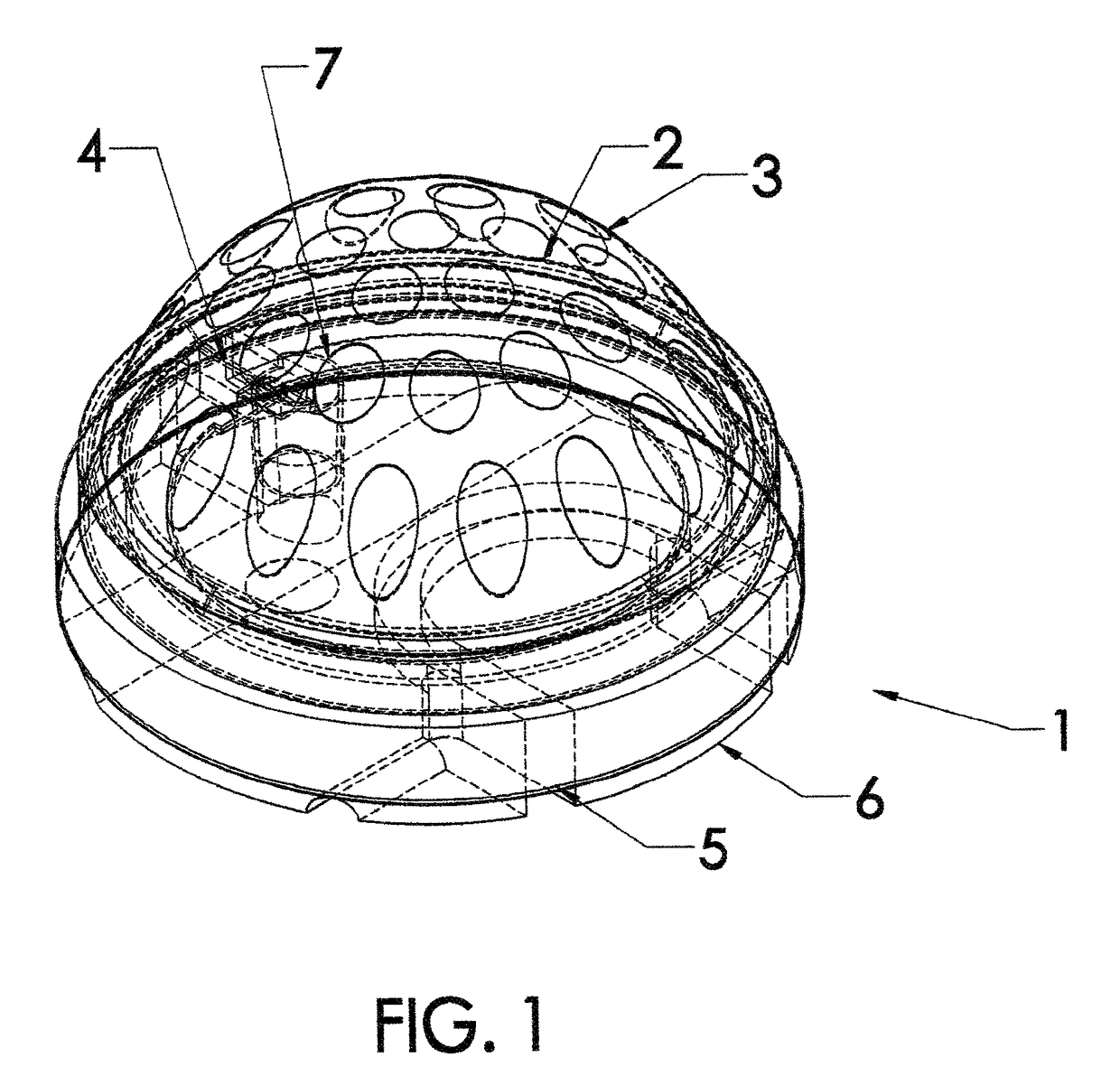
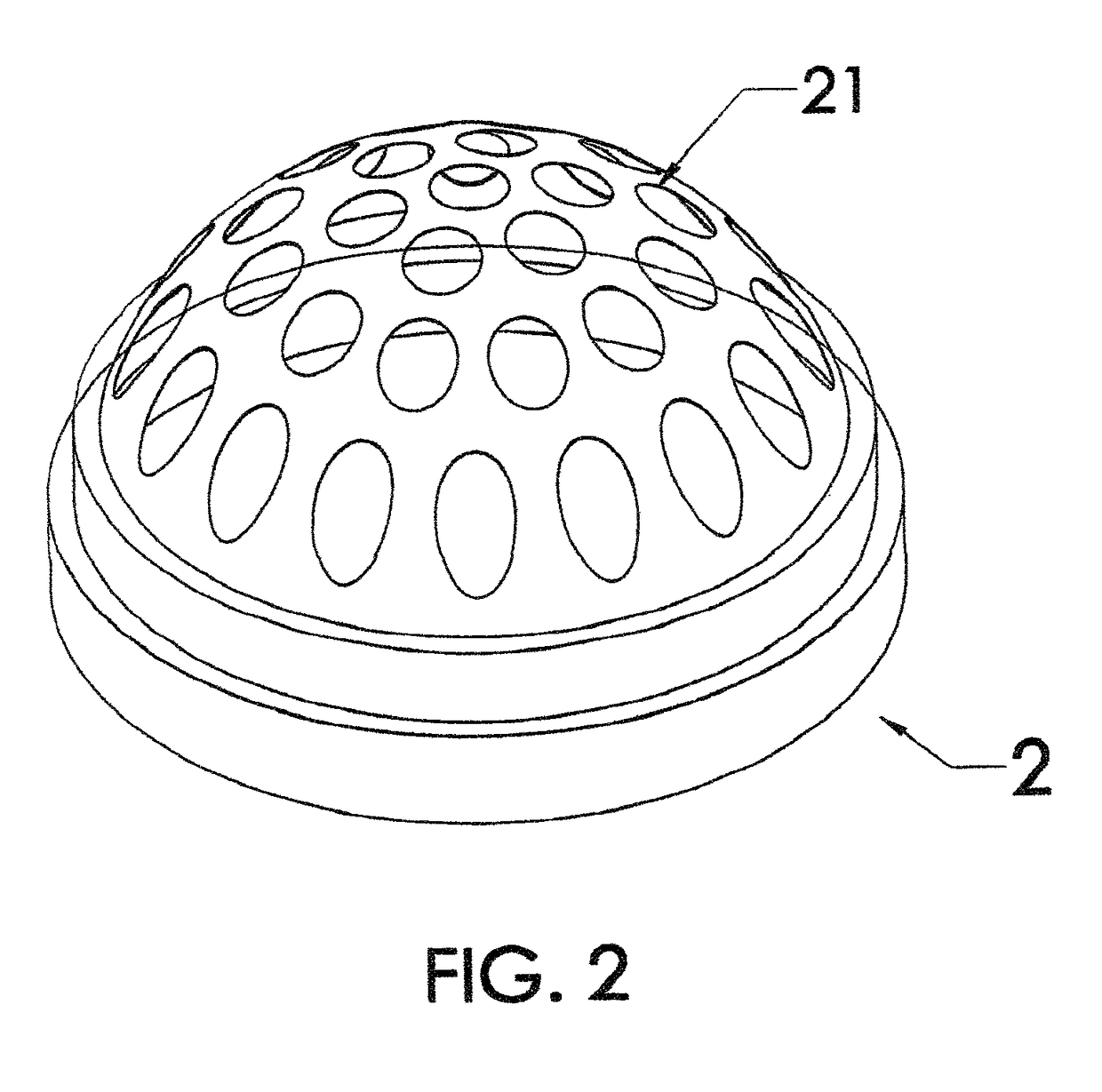
[0025]Referring to FIG. 1 through FIG. 7, the invented water vapor collector 1 consists of an optional capillary net 2, a dome 3, a water conveying channel 4, an optional capillary mat 5, a floatation base 6, and a water tube anchor 7. The capillary net 2 is a perforated fabric or knitted net that has many holes 21 and that can transmit water through capillary forces. The dome 3 is made of a transparent or semitransparent material that allows sun ray to penetrate through. The dome consists of a dome top 31, an upper shoulder 32, an upper curtain wall 33, a lower shoulder 34 and a lower curtain wall 35. The upper shoulder is a short flat surface extended outwards from the rim of the dome top. The upper curtain wall extended downward from the outer rim of the upper shoulder. The lower shoulder extends outwards from the lower rim of the upper curtain wall. The lower curtain wall extends downward from the outer rim of the lower shoulder. The water conveying channel 4 basically is a v-sh...


PUM

PropertyMeasurementUnit
capillary forcesaaaaaaaaaa
flexibleaaaaaaaaaa
weightaaaaaaaaaa

Abstract

A water vapor collector assembly, which consists of an optional capillary net, a dome, a water conveying channel, an optional capillary mat, a floatation base, and a water tube anchor, which many of it can be looped together by ropes and tubes and can float on sea surface to take sun rays to generate freshwater.

Description

CROSS-REFERENCE TO RELATED APPLICATIONS[0001]Not Applicable.BACKGROUND OF THE INVENTION[0002]This invention relates to means to collect water vapors evaporated from a water surface.[0003]Prior patent to Hsia (U.S. Pat. No. 7,654,103 B2) presented a freshwater collection system which comprises a vapor collector field formed by vapor collectors composed of floatable platforms with central holes and domed transparent roofs to collect water vapors which are evaporated by sun rays through the central holes then condensate / condense on the interior surfaces of the domes through sprinkling of waters which are supplied by pumps and sprinkler heads.BRIEF SUMMARY OF THE INVENTION[0004]Obtaining freshwater from seawater or the like can be done by reverse osmosis or evaporation / condensation processes. However, these processes require substantial energy and equipment. They produce relatively costly fresh waters. The uses of sun rays were also attempted. Hsia (U.S. Pat. No. 7,654,103 B2) suggested...

Claims


Application Information

Patent Timeline
Patent Type & Authority Patents(United States)
IPC IPC(8): C02F1/14B01D1/00B01D5/00C02F103/08
CPCB01D1/0005B01D1/0035B01D5/0066C02F1/14B01D5/009C02F2103/08Y02A20/212
Inventor HSIA, CHIH-YUHSIA, MICHAEL JONATHANHSIA, PATRICIA SHIRLEY
Owner HSIA CHIH YU
Learn More