
Louver roller system with an intermittent gear turning mechanism

a technology of gear turning mechanism and roller system, which is applied in the field of roller system of louvers, can solve the problems of insufficient interior light, insufficient daylight in the interior, and inability to uniformly illuminate the inside of the house,

Inactive Publication Date: 2017-10-24
HANGZHOU WOKASOLAR TECH
View PDF16 Cites 1 Cited by
  • Summary
  • Abstract
  • Description
  • Claims
  • Application Information

AI Technical Summary

Benefits of technology

The system provides uniform daylight illumination deep into interiors while preventing glare and overheating, reducing the need for artificial lighting and minimizing energy wastage, enhancing comfort and work efficiency.

Problems solved by technology

One of critical defects of the conventional louver is that indoor daylight illumination could not be uniform.
If the louver blades are turned and adjusted until the light near the window is moderate and glareless, the light deep into the interior is not enough, and it requires artificial lighting.
In addition, people only need moderate light, but no heat in summer, and people need both moderate light and heat in winter, however, for the purpose of reducing light and heat near the window, the louver blades of the conventional louver must be turned to the extent that the louver are almost closed whether in summer or in winter, which results in that the whole room is too dark, and appropriate indoor illumination should be maintained by artificial lighting whether in sunny day or cloudy day, thus causing enormous energy wastage and also reducing people's comfort and work efficiency.
However, this patent application only disclosed the combinatorial structure of the combinatorial louver blades as well as shading and light guiding effects of relatively lifting and turning over the louver blade, and did not disclose a driving mechanism associated with such combinatorial louver.

Method used


Image

  • Louver roller system with an intermittent gear turning mechanism
  • Louver roller system with an intermittent gear turning mechanism
  • Louver roller system with an intermittent gear turning mechanism

Examples


example 1

Turning Cylinder with Two Rollers Mounted therein, a Structure with Two Secondary Louver Blades.

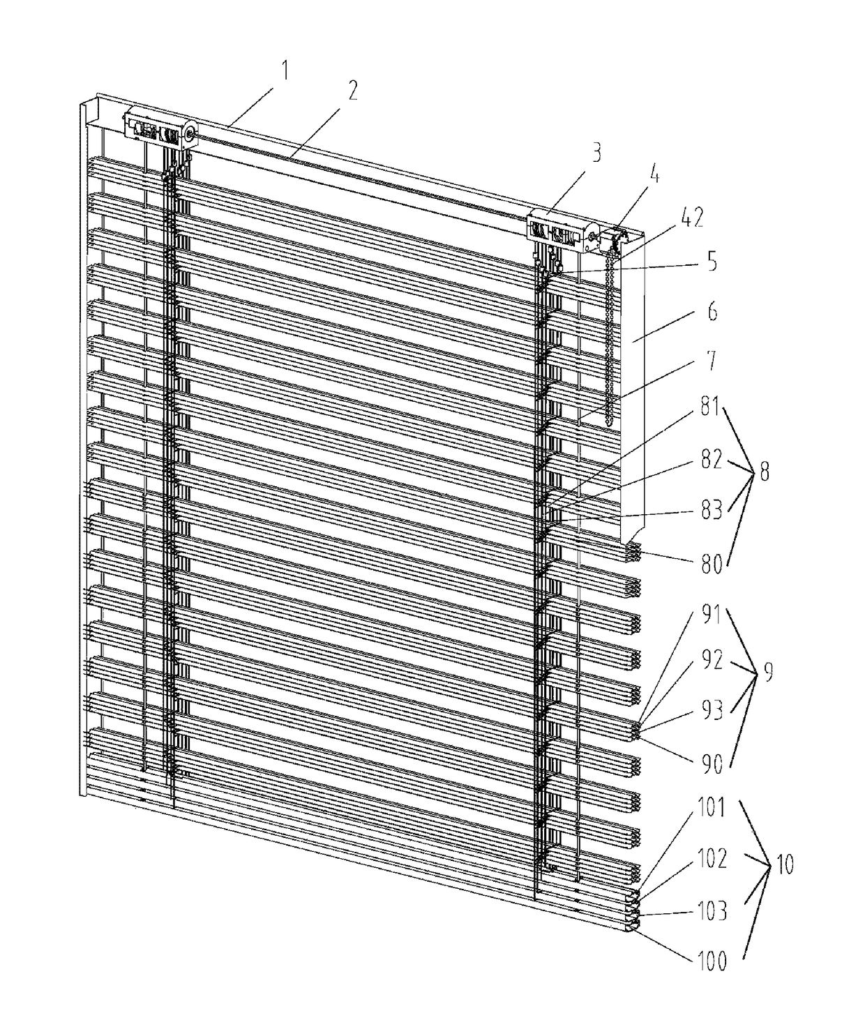
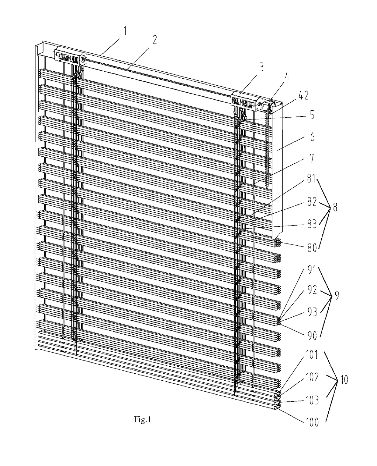
[0064]A movement cycle of relative lifting and turning of combinatorial louver blades of the pitch-variable combinatorial louver with two secondary louver blades is as follows: (1) the primary louver blade 90 is spread over the louver at an equal space, and the secondary louver blades 91 and 92 are superposed on the primary louver blade 90 (corresponding to FIG. 39a); (2) the first secondary louver blade 91 rises to the position D1−D2 relative to the primary louver blade 90, and the second secondary louver blade 92 is still superposed on the primary louver blade 90 (corresponding to FIG. 39b); (3) the first secondary louver blade 91 continues to rise to the position D1 relative to the primary louver blade 90, and meanwhile the second secondary louver blade 92 rises to the position D2 relative to the primary louver blade 90 (corresponding to FIG. 39c); (4) the primary and secondary louver ...

example 2

Turning Cylinder with Three Rollers Mounted therein, a Structure with Three Secondary Louver Blades (Dual Binary Pitch)

[0087]A movement cycle of relative lifting and turning of combinatorial louver blades of the pitch-variable combinatorial louver with three secondary louver blades (dual binary pitch) is as follows: (1) the primary louver blade 90 is spread over the louver at an equal space, and the secondary louver blades 91, 92 and 93 are sequentially superposed on the primary louver blade 90 (corresponding to FIG. 40a); (2) the first secondary louver blade 91 and the second secondary louver blade 92 rises to the position D2 relative to the primary louver blade 90 (corresponding to FIG. 40b); (3) the second secondary louver blade 92 is detached from the first secondary louver blade 91 and is located at the position D2, the first secondary louver blade 91 and the third secondary louver blade 93 rise a distance D3 relative to the primary louver blade 90, at this point the first seco...


PUM


Abstract

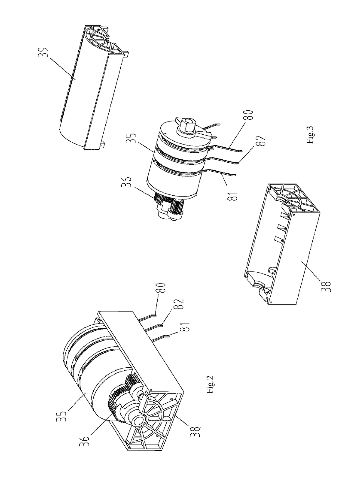
The invention discloses a louver roller system with an intermittent gear turning mechanism, comprising a base and a top cover, wherein a roller mechanism and an intermittent gear turning mechanism are mounted on the base, the roller mechanism is wound with ladder tapes, the roller mechanism is in axial connection with the intermittent gear turning mechanism, and the roller mechanism and the intermittent gear turning mechanism are driven to rotate by a square shaft. The roller mechanism controls horizontal rising and falling of secondary louver blades, and the roller within the roller mechanism rotates to wind or unwind the ladder tapes thereon and sequentially drives various secondary louver blades to rise and fall horizontally. When various secondary louver blades rise to a predetermined position, the intermittent gear turning mechanism drives a turning cylinder to rotate, so as to achieve turning of all louver blades.

Description

FIELD OF THE INVENTION[0001]The invention relates to a louver, in particular to a roller system of the louver.BACKGROUND[0002]Conventional louver consists of louver blades with arch-up cross sections, halyards, ladder tapes, a top rail and a base rail. A rotary actuator with self-locking function, a rotating shaft, several winding halyards and rollers for controlling the ladder tapes are installed in the top rail, the rotating shaft passes through the rotary actuator and the roller, there are ladder tapes between the top rail and the base rail, the lower ends of the ladder tapes are in fixed connection with the base rail, and two upper ends of the ladder tapes are butted and sheathed on the roller; a plurality of louver blades in parallel are put in the breast line of the ladder tape, a through hole is set at a symmetric center of the cross section of the louver blade to allow the halyard to pass through, the lower end of the halyard is in fixed connection with the base rail, and th...

Claims


Application Information

Patent Timeline
Patent Type & Authority Patents(United States)
IPC IPC(8): E06B9/322E06B9/303
CPCE06B9/303E06B9/322
Inventor ZHANG, YIFEIWU, CHENGSHANG
Owner HANGZHOU WOKASOLAR TECH
Learn More