
Golf club and golf club head structures

a golf club and golf club head technology, applied in the field of golf clubs and golf club heads, can solve the problems of surprising sound, affecting the swing, affecting the distance, direction, etc., and achieving the effect of improving the weight distribution

Active Publication Date: 2017-10-24
KARSTEN MFG CORP
View PDF1012 Cites 24 Cited by
  • Summary
  • Abstract
  • Description
  • Claims
  • Application Information

AI Technical Summary

Benefits of technology

The patent text discusses golf clubs with weighted golf club heads, specifically using a void in the head and adjustable weight arrangements. The weight can be inserted and adjusted in multiple positions to change the weighting characteristics of the head. The receiving tube has threads and a fastener to secure the weight. The technical effect of the invention is to improve the weight distribution and adjustability of golf club heads, leading to better shots and more accurate hits.

Problems solved by technology

If a club head makes an unpleasant, undesirable, or surprising sound at impact, a user may flinch, give up on his / her swing, decelerate the swing, lose his / her grip, and / or not completely follow-through on the swing, thereby affecting distance, direction, and / or other performance aspects of the swing and the resulting ball motion.
User anticipation of this unpleasant, undesirable, or surprising sound can affect a swing even before the ball is hit.
When the center of gravity is spaced to a side of the point of engagement, however, the golf ball may fly in an unintended direction and / or may follow a route that curves left or right, including ball flights that often are referred to as “pulls,”“pushes,”“draws,”“fades,”“hooks,” or “slices.” Similarly, when the center of gravity is spaced above or below the point of engagement, the flight of the golf ball may exhibit more boring or climbing trajectories, respectively.
In pursuit of such designs, club designers also face a challenge of maintaining a club head having a traditional aesthetic look desired by most golfers.
While certain golf club and golf club head designs according to the prior art provide a number of advantageous features, they nevertheless have certain limitations.

Method used


Image

  • Golf club and golf club head structures
  • Golf club and golf club head structures
  • Golf club and golf club head structures

Examples


Embodiment Construction

[0042]In the following description of various example structures in accordance with the invention, reference is made to the accompanying drawings, which form a part hereof, and in which are shown by way of illustration various example articles, including one or more golf club or golf club head structures. Additionally, it is to be understood that other specific arrangements of parts and structures may be utilized and structural and functional modifications may be made without departing from the scope of the present invention. Also, while the terms “top,”“bottom,”“front,”“back,”“rear,”“side,”“underside,”“overhead,” and the like may be used in this specification to describe various example features and elements of the invention, these terms are used herein as a matter of convenience, e.g., based on the example orientations shown in the figures and / or the orientations in typical use. Nothing in this specification should be construed as requiring a specific three dimensional or spatial ...


PUM


Abstract

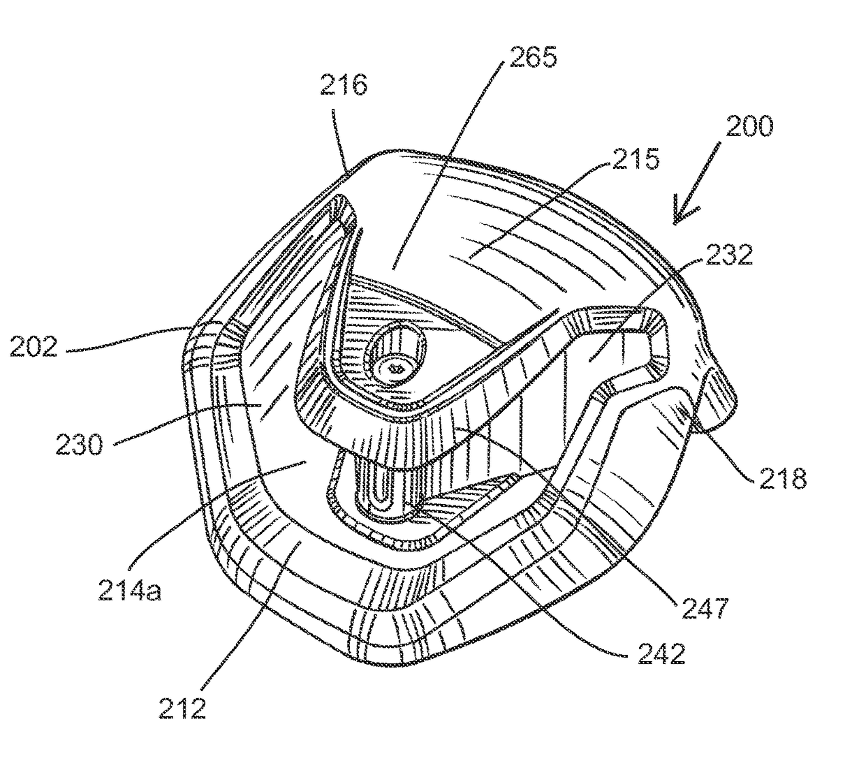
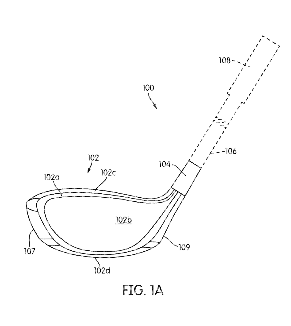
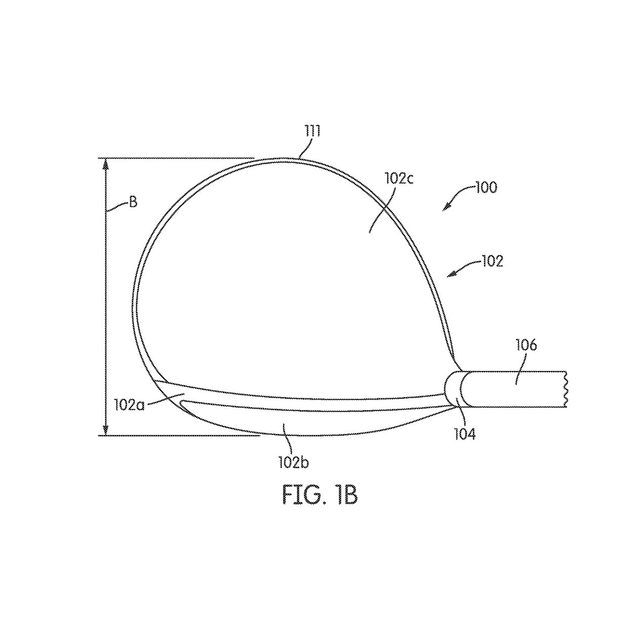
A golf club head has a body having a ball striking face, a rear opposite the ball striking face, a crown, a sole, a heel, and a toe, the body having a void defined by a peripheral edge on the sole. The body further defines a cover that extends over the void and forms at least a portion of the crown. At least a portion of the peripheral edge of the void includes a lip extending from the peripheral edge inwardly into the void. The golf club head may additionally or alternately include one or more weight receptacles connected to the sole and having an opening in the sole, such that each weight receptacle is configured to receive insertion of a weight through the opening.

Description

CROSS-REFERENCE TO RELATED APPLICATIONS[0001]The present application claims the benefit of and is a continuation-in-part of U.S. patent application Ser. No. 13 / 593,253, filed Aug. 23, 2012, which application claims the benefit of and is a non-provisional of U.S. Provisional Application No. 61 / 526,326, filed on Aug. 23, 2011, and U.S. Provisional Application No. 61 / 598,832, filed on Feb. 14, 2012, and which application also claims priority to and is a continuation-in-part of U.S. patent application Ser. No. 13 / 250,051, filed on Sep. 30, 2011, and issued as U.S. Pat. No. 8,668,595 on Mar. 11, 2014, which claims the benefit of and is a non-provisional of U.S. Provisional Application No. 61 / 480,332, filed Apr. 28, 2011, and which application further claims priority to and is a continuation-in-part of U.S. patent application Ser. No. 12 / 723,951, filed on Mar. 15, 2010, which is a continuation-in-part of U.S. patent application Ser. No. 12 / 356,176, filed on Jan. 20, 2009, and issued as U....

Claims


Application Information

Patent Timeline
Patent Type & Authority Patents(United States)
IPC IPC(8): A63B53/04A63B53/06A63B60/54
CPCA63B53/06A63B53/0466A63B53/047A63B53/0487A63B60/54A63B2225/01A63B2053/0408A63B2053/0433A63B2053/0437A63B2053/0491A63B2053/045A63B60/52A63B60/02A63B53/0433A63B53/045A63B60/00
Inventor TAYLOR, MICHAEL G.WALLANS, MICHAELSTITES, JOHN T.JONES, SHERRY L.
Owner KARSTEN MFG CORP
Learn More