
Tape Dispenser

a dispenser and tape technology, applied in the field of tape dispensers, can solve the problems of increasing manual strain and fatigue, reducing the use effect of tape, and not providing additional means for dispensing tape lengths, etc., and achieve the effect of reducing manual strain and improving grip placemen

Active Publication Date: 2016-01-07
JOE GALLEGOS DESIGN LLC
View PDF9 Cites 2 Cited by
  • Summary
  • Abstract
  • Description
  • Claims
  • Application Information

AI Technical Summary

Benefits of technology

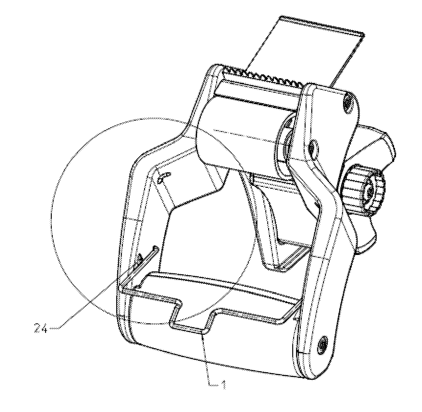
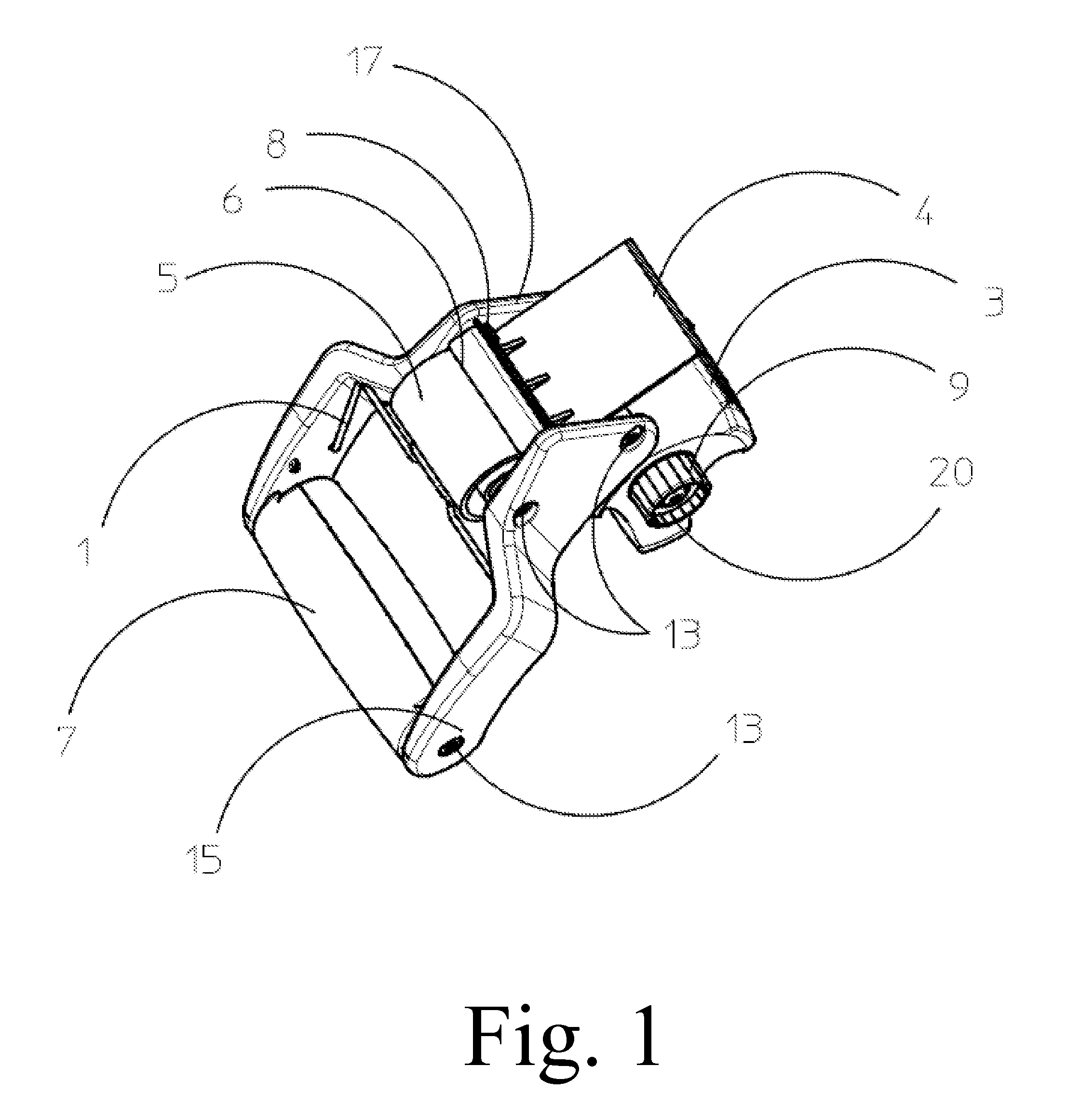
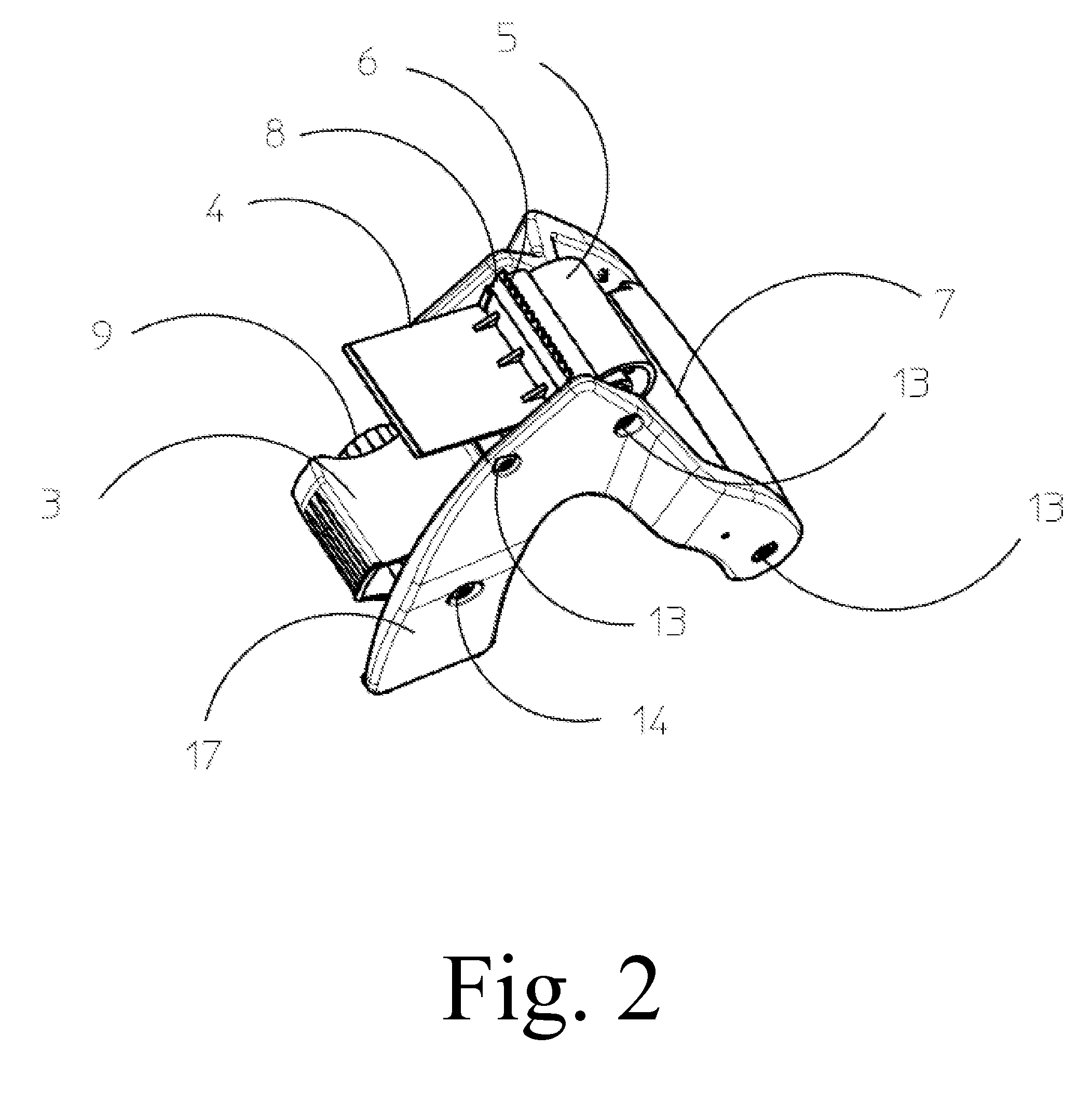
The present invention is a tape gun with an ellipsoid shaped handle that provides greater flexibility and stability when dispensing packaging tape onto common containment items such as cardboard boxes. The handle's orientation and design improve the user's ability to apply force and distribute the weight of the components. The tape gun can be easily attached to a bracket or used as a temporary cradle style mounting. Additionally, the invention reduces manual strain by improving the placement of the grip and distribution of centers of gravity. Furthermore, the invention provides a stable means for using the tape gun as a table top dispenser, ensuring the product remains stable during dispensing and cutting off.

Problems solved by technology

Tape dispensers currently found in the market all employ pistol grip handles which result in severe hand, wrist, and forearm strain in combination with the resultant awkwardly applied forces from poorly located centers of gravity between the tape spool and the handle.
Also, other similar products do not provide additional means for dispensing lengths of tape without the need for additional bracket or hardware.
Due to their design, these pistol grips are also oriented in a location that is an excessively long moment arm distance from the other two functional components: the tape roll and the cut-off device, which maximizes manual strain and fatigue during use.
The weight distribution among all three components (tape roll, pistol grip, and cut-off mechanism) are less than optimum which results in excessive wrist and forearm fatigue and strain.
The pistol grip limits the amount of angular range that a user can apply while applying tape to a box from multiple sides, angles and directions.
The shape, location and poor weight distribution of the pistol grip does not allow for fingertip articulation limiting the ability to apply quick, subtle and varying force and motion while negotiating a tape application stroke at changing angles throughout.

Method used


Image

  • Tape Dispenser
  • Tape Dispenser
  • Tape Dispenser

Examples


Embodiment Construction

[0028]In the following detailed description of the invention of exemplary embodiments of the invention, reference is made to the accompanying drawings (where like numbers represent like elements), which form a part hereof, and in which is shown by way of illustration specific exemplary embodiments in which the invention may be practiced. These embodiments are described in sufficient detail to enable those skilled in the art to practice the invention, but other embodiments may be utilized and logical, mechanical, electrical, and other changes may be made without departing from the scope of the present invention. The following detailed description is, therefore, not to be taken in a limiting sense, and the scope of the present invention is defined only by the appended claims.

[0029]In the following description, numerous specific details are set forth to provide a thorough understanding of the invention. However, it is understood that the invention may be practiced without these specifi...


PUM


Abstract

A tape dispenser with an ellipsoid shaped handle providing an optimized grip handle in a parallel axis with the tape spool axis. The ellipsoid shaped handle of the present invention provides an optimized grip angle orientation for directly dispensing packaging tape. The ellipsoid shaped handle of the present invention provides greater freedom of angular movement, articulation, and force application while providing improved weigh distribution of the working components (handle, tape spool, and cut off device). The tape dispenser is comprised of: a u-shaped main body and arm, which are attached to a plurality of interior components removeably affixed between them by a plurality of screws. Interior components are a stem, small support, large support, blade, roller, cushion handle, tape end guide, blade, burnisher, and platen. The u-shaped main body defines a base structure for the dispenser to sit solidly on top of a flat, horizontal surface.

Description

CROSS REFERENCE TO RELATED APPLICATIONS[0001]This application claims priority from U.S. Provisional Patent Application Ser. No. 62 / 019,904, entitled “Combination Tape Dispenser”, filed on 2 Jul. 2014. The benefit under 35 USC §119(e) of the United States provisional application is hereby claimed, and the aforementioned application is hereby incorporated herein by reference.SEQUENCE LISTING OR PROGRAM[0002]Not ApplicableTECHNICAL FIELD OF THE INVENTION[0003]The present invention relates generally to tape dispensers. More specifically, the present invention relates to tape dispensers with ergonomic handles.BACKGROUND OF THE INVENTION[0004]Tape dispensers currently found in the market all employ pistol grip handles which result in severe hand, wrist, and forearm strain in combination with the resultant awkwardly applied forces from poorly located centers of gravity between the tape spool and the handle. Also, other similar products do not provide additional means for dispensing lengths...

Claims


Application Information

Patent Timeline
Patent Type & Authority Applications(United States)
IPC IPC(8): B65H35/00
CPCB65H35/0033B65H35/0026Y10T225/20Y10T225/245Y10T225/257Y10T225/282
Inventor GALLEGOS, ROBERT, JOSEPH
Owner JOE GALLEGOS DESIGN LLC
Learn More