
Acoustic wave detection probe and photoacoustic measurement apparatus provided with the same

a technology of acoustic wave detection and photoacoustic measurement, which is applied in the direction of instruments, ultrasonic/sonic/infrasonic diagnostics, mechanical vibration separation, etc., can solve problems such as solving them, and achieve the effect of reducing the generation of artifacts arising from the projection of measuring ligh

Active Publication Date: 2017-10-17
FUJIFILM SONOSITE
View PDF20 Cites 4 Cited by
  • Summary
  • Abstract
  • Description
  • Claims
  • Application Information

AI Technical Summary

Benefits of technology

The present invention aims to provide an acoustic wave detection probe that can reduce artifacts during photoacoustic measurements. The invention achieves this by using an acoustic lens and a surface portion of the housing that have optical properties that prevent light reflected from the measurement target from passing through the acoustic lens and being absorbed by the acoustic wave transducer or being absorbed by the acoustic lens. The technical effect is to improve the accuracy of photoacoustic measurements.

Problems solved by technology

It is difficult, however, to solve this problem by simply satisfying the six requirements described above.

Method used


Image

  • Acoustic wave detection probe and photoacoustic measurement apparatus provided with the same
  • Acoustic wave detection probe and photoacoustic measurement apparatus provided with the same
  • Acoustic wave detection probe and photoacoustic measurement apparatus provided with the same

Examples


first embodiment

[First Embodiment of Photoacoustic Measurement Apparatus]

[0063]Next, a first embodiment of photoacoustic measurement apparatus will be described. In the present embodiment, a detailed description will be made of a case in which the photoacoustic measurement apparatus is a photoacoustic image generation apparatus that generates a photoacoustic image based on photoacoustic signals. FIG. 6 is a block diagram of the photoacoustic image generation apparatus 10 of the present embodiment, illustrating the configuration thereof.

[0064]The photoacoustic image generation apparatus 10 of the present embodiment includes a probe 11 according to the present invention, an ultrasonic unit 12, a laser unit 13, an image display means 14, and an input means 16.

[0065]The laser unit 13 outputs, for example, laser light L as measuring light to be projected onto a subject M. The laser unit 13 is configured to output the laser light L, for example, by receiving a trigger signal from a control means 29. The ...

second embodiment

[Second Embodiment of Photoacoustic Measurement Apparatus]

[0082]A second embodiment of photoacoustic measurement apparatus will be described next. Also in the present embodiment, a detailed description will be made of a case in which the photoacoustic measurement apparatus is a photoacoustic image generation apparatus. FIG. 7 is a block diagram of the photoacoustic image generation apparatus 10 of the present embodiment, illustrating the configuration thereof. The present embodiment differs from the first embodiment in that it generates an ultrasonic image in addition to the photoacoustic image. Therefore, the detailed description of the components identical to those of the first embodiment is omitted unless otherwise specifically required.

[0083]The photoacoustic image generation apparatus 10 of the present embodiment includes a probe 11 according to the present invention, an ultrasonic unit 12, a laser unit 13, an image display means 14, and an input means 16, as in the first embod...


PUM

PropertyMeasurementUnit
particle sizeaaaaaaaaaa
wt %aaaaaaaaaa
acoustic velocityaaaaaaaaaa

Abstract

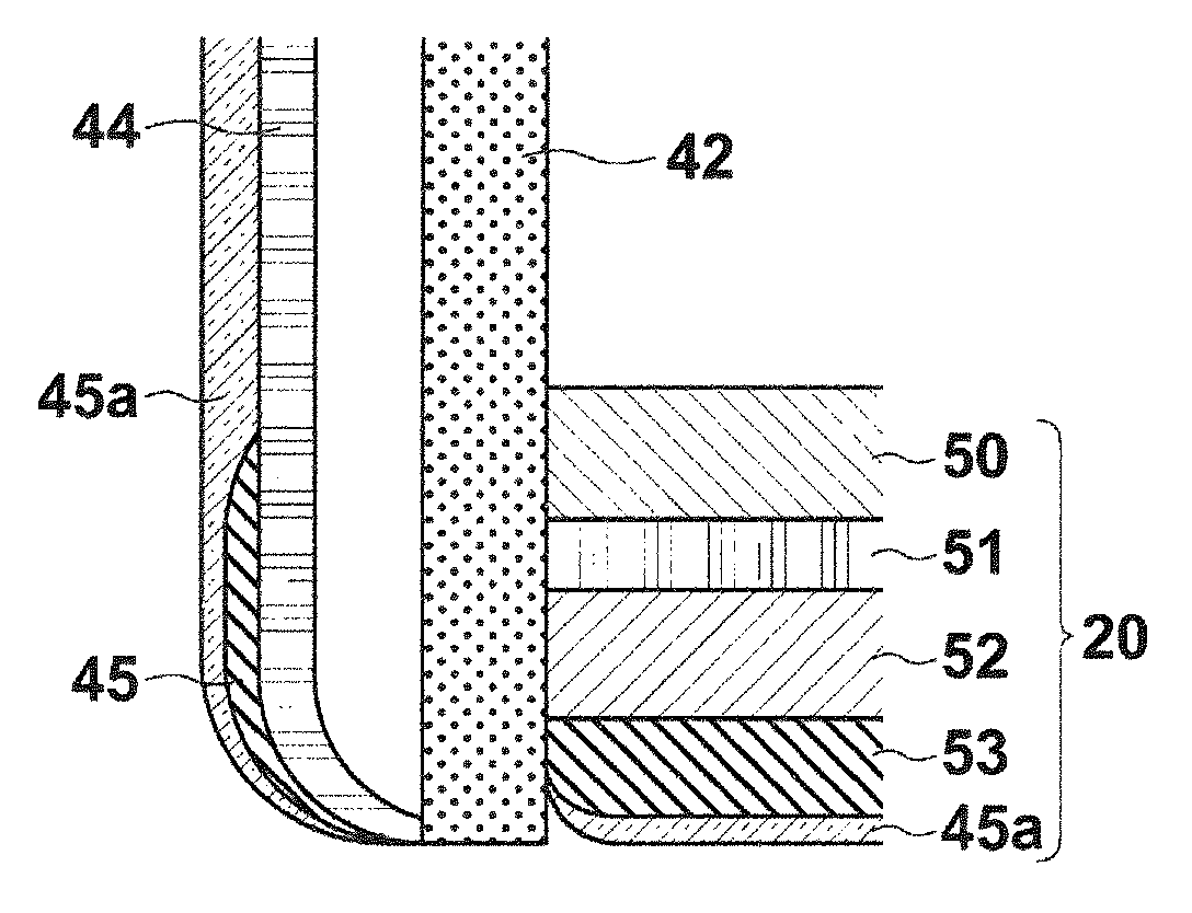
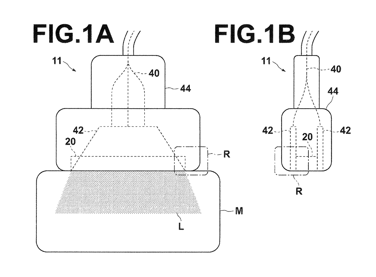
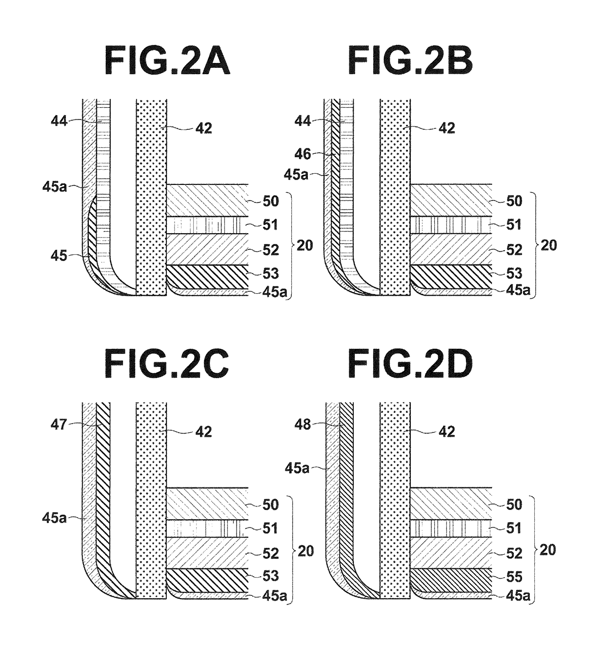
An acoustic wave detection probe includes a light projection section that emits measuring light to be projected onto a subject, an acoustic wave transducer disposed adjacent to the light projection section and capable of detecting an acoustic wave, an acoustic lens provided on a detection side of the acoustic wave transducer, and a housing accommodating the light projection section, the acoustic wave transducer, and the acoustic lens, in which the acoustic lens and a surface portion of the housing adjacent to the acoustic lens are formed to have an optical property in which the average diffuse reflection factor is 85% or more and the average absorption factor is 10% or less in a wavelength range of the measuring light.

Description

CROSS-REFERENCE TO RELATED APPLICATIONS[0001]This application is a Continuation of PCT International Application No. PCT / JP2013 / 000659 filed on Feb. 7, 2013, which claims priority under 35 U.S.C. §119 (a) to Japanese Patent Application No. 2012-028372 filed on Feb. 13, 2012 and Japanese Patent Application No. 2013-019302 filed on Feb. 4, 2013, the contents of which are hereby expressly incorporated herein by reference in their entirety.TECHNICAL FIELD[0002]The present invention relates to a probe to be applied to a measurement target to detect an acoustic wave, and a photoacoustic measurement apparatus.BACKGROUND ART[0003]Acoustic wave detection probes have been conventionally used, for example, in ultrasonic imaging devices and photoacoustic imaging devices used for diagnosis, fish finders used in fishery, and the like. Such probes have acoustic lenses incorporated therein for focusing acoustic wave beams to improve resolution.[0004]For example, Japanese Unexamined Patent Publicati...

Claims


Application Information

Patent Timeline
Patent Type & Authority Patents(United States)
IPC IPC(8): G01N29/24G01N29/04A61B8/00G01N29/22A61B5/00B06B1/06
CPCG01N29/22A61B5/0035A61B5/0095A61B8/4416B06B1/0644G01N29/043G01N29/221G01N29/2418G01N29/2437
Inventor IRISAWA, KAKUYAMAMOTO, KATSUYA
Owner FUJIFILM SONOSITE
Learn More