
Laparascope and endoscope cleaning and defogging device

a technology of endoscope and cleaning device, which is applied in the field of laparoscopic and endoscope surgery, can solve the problems of camera and camera dislocating from the device and becoming damaged

Active Publication Date: 2017-10-03
BUFFALO FILTER
View PDF61 Cites 2 Cited by
  • Summary
  • Abstract
  • Description
  • Claims
  • Application Information

AI Technical Summary

Benefits of technology

[0004]The new apparatus and system described and illustrated herein is designed to improve and / or maximize the visualization of the scope during surgical procedures.
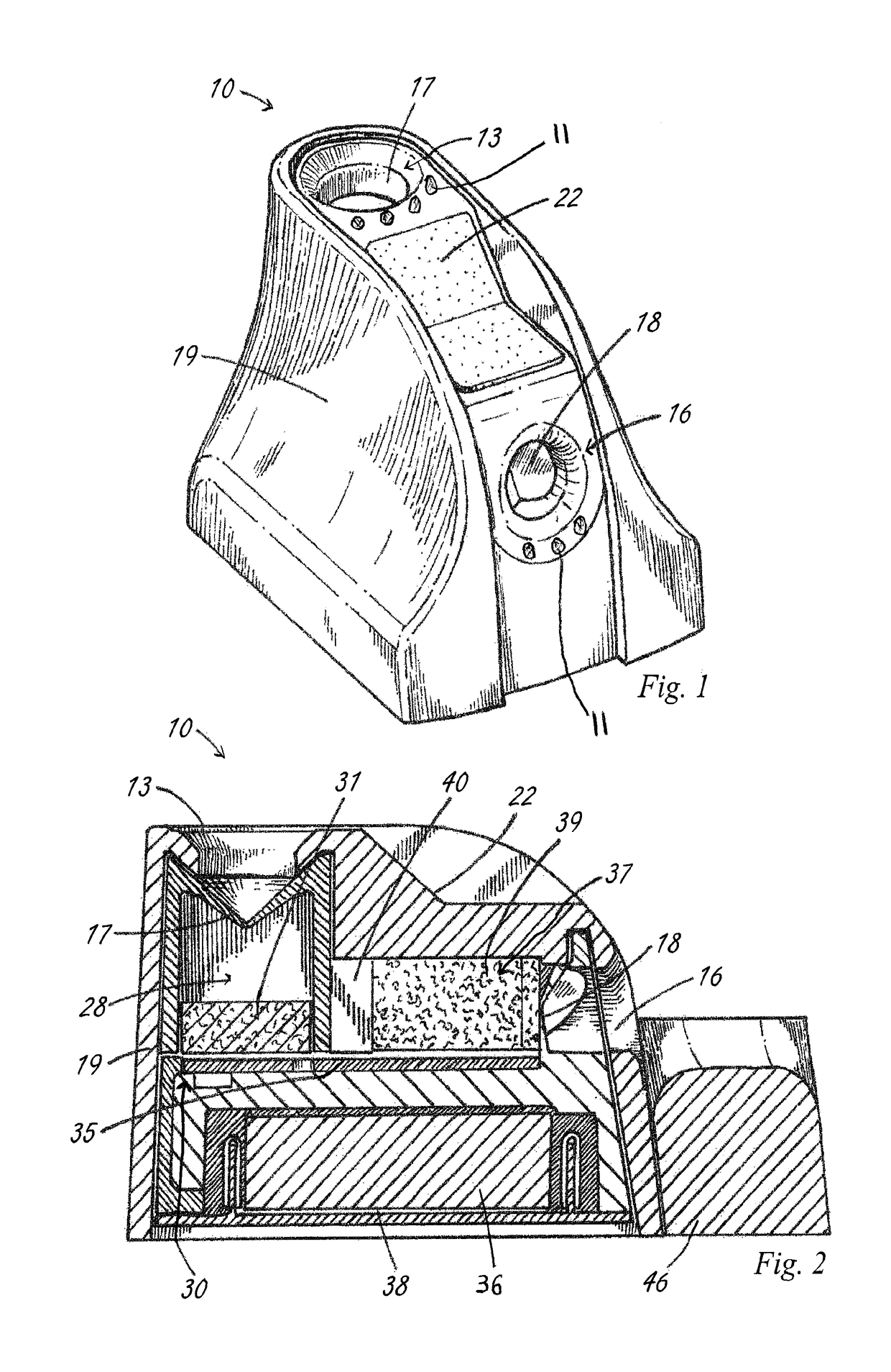
[0005]In one aspect, the device has a port located horizontally that is used to warm the scope prior to insertion into the body cavity / surgical site. The scope enters the cavity between two bodies of absorbent material that may or may not contain fluid. The absorbent material is arranged such that the passage of a scope would be accommodated for a size range of 1 mm up to 15 mm in diameter. A circuit board is located on the bottom of the chamber that has a design element used to warm the liquid to a temperature sufficient to reduce or eliminate issues related to temperature differences between the surrounding environment and the body of the patient. When the scope is located between the two absorbent bodies, the heat generated by the circuit board is transferred to the scope, warming it in preparation for surgery. Also within this chamber is a V-shaped member of white, non-porous material that may be used to white balance the camera. The V-shape allows for multiple different sizes of scopes ranging from 1 mm to 15 mm to accurately white balance per the camera system procedure.
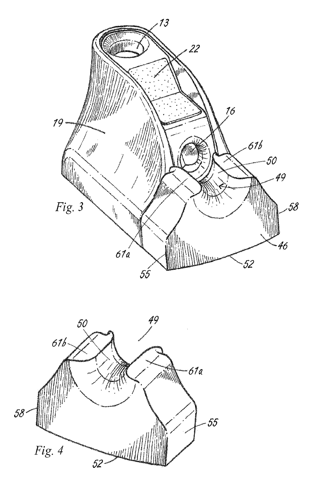
[0006]In another aspect, a separate stand or cradle is supplied with the device to hold the scope during the warming procedure. When the scope is aligned horizontally, there is a chance that the scope and camera could dislodge from the device and become damaged due to a fall or shock. The stand is designed and supplied with the main device to cradle the scope and camera while in the horizontal position, limiting the possibility of damage from fall or shock.
[0008]In another aspect, the device has a port located vertically that is used to clean and warm the scope after use in the surgical site. The scope punctures the initial membrane and enters the cavity comprised of a cleaning surface and liquid that has been warmed by the circuit board. The cleaning surface may be comprised of a porous material such as a sponge or non-woven material or it could be comprised of a silicone or similar flexible material in a unique pattern or design for cleaning of the lens. The cleaning surface, along with a warm fluid located in the chamber is used to remove debris and / or fog that has accumulated on the lens during surgery that limits visualization for the user.
[0009]In another aspect, light emitting diodes are included in the device to illuminate both or either of the ports for identification. The LED(s) would illuminate once the heating element has been activated, confirming to the user the device was in-use. Also, during use the illumination of the port or ports would aid the user in identification of the device, especially in operation within a dimly lit room, typical of laparoscopic procedures.

Problems solved by technology

When the scope is aligned horizontally, there is a chance that the scope and camera could dislodge from the device and become damaged due to a fall or shock.

Method used


Image

  • Laparascope and endoscope cleaning and defogging device
  • Laparascope and endoscope cleaning and defogging device
  • Laparascope and endoscope cleaning and defogging device

Examples


Embodiment Construction

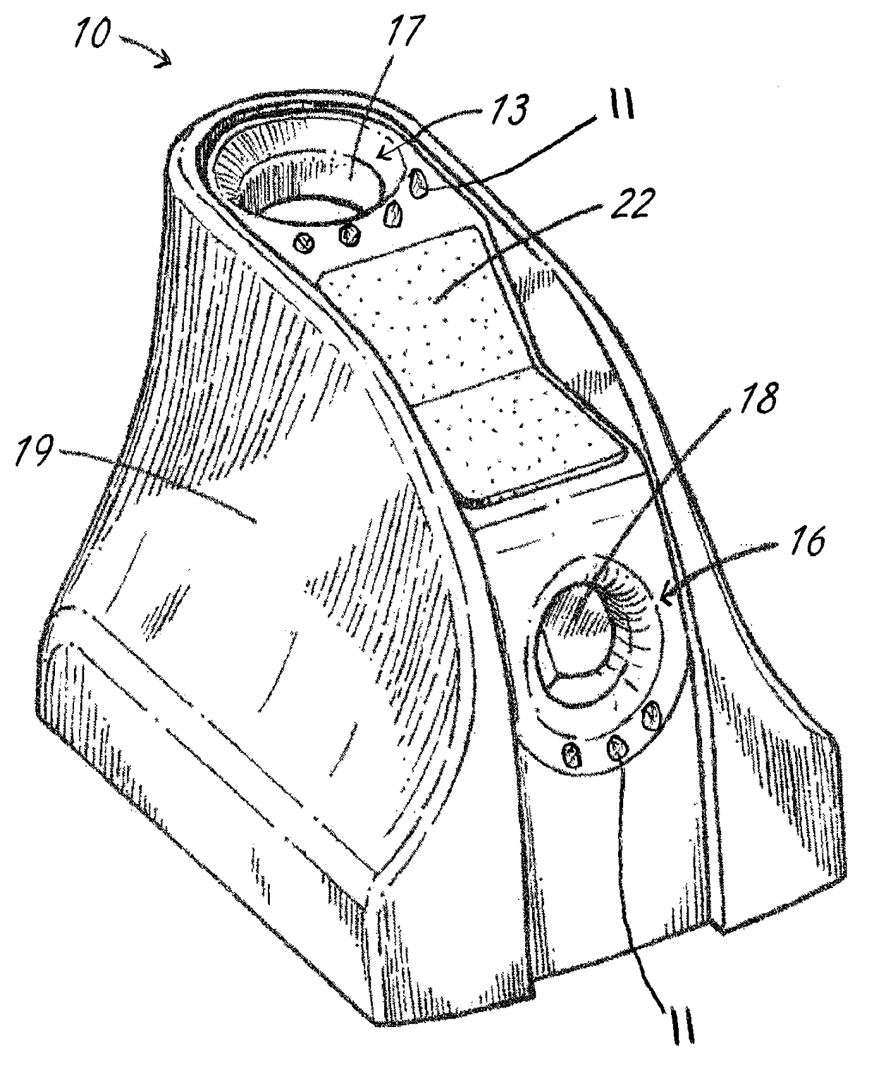
[0028]Turning to FIG. 1, the scope cleaning device 10 has a first opening 13 for receiving a generally vertically oriented scope and a second opening 16 for receiving a generally horizontally oriented scope. A plurality of illumination devices such as light emitting diodes 11 may be disposed around the openings 13, 16 to facilitate the insertion of the surgical scopes in darker environments. The openings 13, 16 may be sealed by a frangible disc 17, 18 made of an elastomeric material or the like. The seals are provided to seal the cleaning solution in the device prior to use. The scope cleaning device has a housing 19 that is closed and sealed to protect the internal compartments from exposure to outside elements. A microfiber wipe 22 may be mounted to the exterior of the housing 19 such that a scope 115 (FIG. 13) may be brought into contact with the wipe 22 to remove debris. The device 10 uses separate compartments to clean, warm and white balance a scope.

[0029]Turning to FIG. 2, th...


PUM


Abstract

A laparascope and endoscope cleaning and defogging device with a port located horizontally that is used to warm the scope prior to insertion into the body cavity / surgical site. The scope punctures the initial membrane and enters the cavity between two bodies of absorbent material that contain fluid. The absorbent material is arranged such that the passage of a scope would be accommodated for different sizes of surgical scopes. A circuit board is located on the bottom of the chamber that has a design element used to warm the liquid to a temperature equal to or greater than the temperature of the proposed surgical environment. When the scope is located between the two absorbent bodies, the heat generated by the circuit board is transferred via the liquid and contacts the scope, warming it in preparation for surgery.

Description

CROSS-REFERENCE TO RELATED APPLICATION[0001]The present invention claims priority benefit of U.S. Provisional Patent Application No. 61 / 989,220 filed May 6, 2014 and entitled “Laparascope and Endoscope Cleaning and Defogging Device,” which is hereby incorporated by reference.TECHNICAL FIELD[0002]The present invention relates generally to laparoscopic and endoscopic surgery, and more specifically, to a device that warms, cleans, and defogs the laparoscope or endoscope before and during medical procedures that utilize that technology for visualization.BACKGROUND[0003]A laparoscope or endoscope is used in conjunction with a camera system for visualization during surgical procedures. When the scope is introduced from ambient room temperature into a cavity at body temperature, the rapid change causes the lens to fog. During surgery, the introduction of surgical tools such as an electrosurgical device deliver energy, creating heat, and vaporizes the intracellular fluid, which increases th...

Claims


Application Information

Patent Timeline
Patent Type & Authority Patents(United States)
IPC IPC(8): A61B1/12B08B3/10B08B1/00A61B1/00A61M25/00
CPCA61B1/123A61B1/00131A61B1/126A61B1/127A61B1/128B08B1/001B08B3/10A61M2025/0019A61B90/70A61B2090/701
Inventor MILLER, MICHAEL J.KELLNER, WILLIAM J.LIZAUCKAS, III, ANTHONY L.PEPE, GREGORYBONANO, SAMANTHA
Owner BUFFALO FILTER
Learn More