
Long Range Radio Frequency Identification System

a radio frequency identification and long-range technology, applied in the direction of instruments, electrical equipment, computing, etc., can solve the problems of inability to obtain the full coherent processing gain, inability to implement very long-range matching filters, and poor performance, so as to maximize the wireless range, precise positioning of rfid tags, and large coherent processing gains

Active Publication Date: 2011-02-10
RING LLC
View PDF17 Cites 33 Cited by
  • Summary
  • Abstract
  • Description
  • Claims
  • Application Information

AI Technical Summary

Benefits of technology

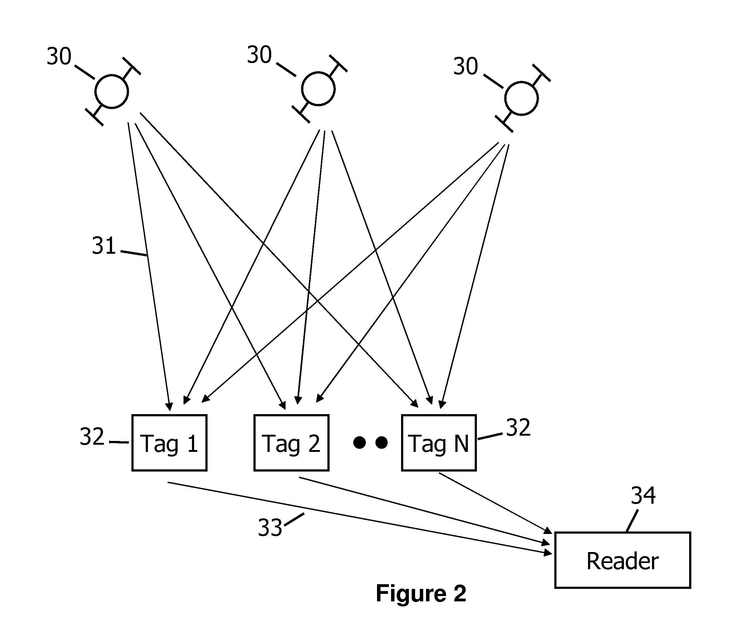
[0004]This disclosure describes systems and methods for construction of long range radio frequency identification systems. Described is an approach using the global positioning system (GPS) to frequency synchronize oscillators in RFID tags and RFID readers which enables very large coherent processing gains to be achieved, thus maximizing the wireless range. The construction of signals called Block Pseudo Noise sequences is described which allow for the efficient implementation of decoders to decode very weak signals. Furthermore, in long range RFID systems, it is important to be able to locate RFID tags in an efficient manner. A new approach called Asynchronous Time Difference of Arrival (ATDOA) is described which allow for precise positioning of RFID tags without the need for precise time synchronization amongst readers. In RFID systems with multiple readers and tags, it is important to reduce interference between tags and readers, new techniques are described which efficiently minimize interference. The subject matter includes a system for long-range RFID communication, including one or more RFID readers and one or more RFID tags. Some or all of the readers and tags may have an oscillator frequency synchronization circuit.

Problems solved by technology

This technique was proposed due to the fact that the transmitter and receiver are never perfectly frequency synchronized, consequently attempting to match filter over a long segment would result in poor performance.
Furthermore, the required complexity to matched filter over long periods of time increases linearly with the correlation time, making it cost prohibitive to implement very long matched filters.
The disadvantage of this approach is that one cannot obtain the full coherent processing gain.

Method used


Image

  • Long Range Radio Frequency Identification System
  • Long Range Radio Frequency Identification System
  • Long Range Radio Frequency Identification System

Examples


Embodiment Construction

[0017]Some of the terms used within the application are described here.

AC—Alternating Current

[0018]Amplitude Modulation—The variation of the signal strength of the transmit signal in relation to the information being sent.

Coherent Processing—Matched Filtering when the unknown signal is in frequency and phase synchronization with the known template signal.

GPS —Global Positioning System

[0019]Matched Filter—The correlation of a known signal, or template with an unknown signal to detect the presence of the known template in the unknown signal.

Pseudo Noise Sequence—A sequence of numbers with pseudorandom properties intended to simulate white noise.

Pulse Position Modulation—A form of signal modulation in which M message bits are encoded by transmitting a single pulse in one of 2M possible time-shifts.

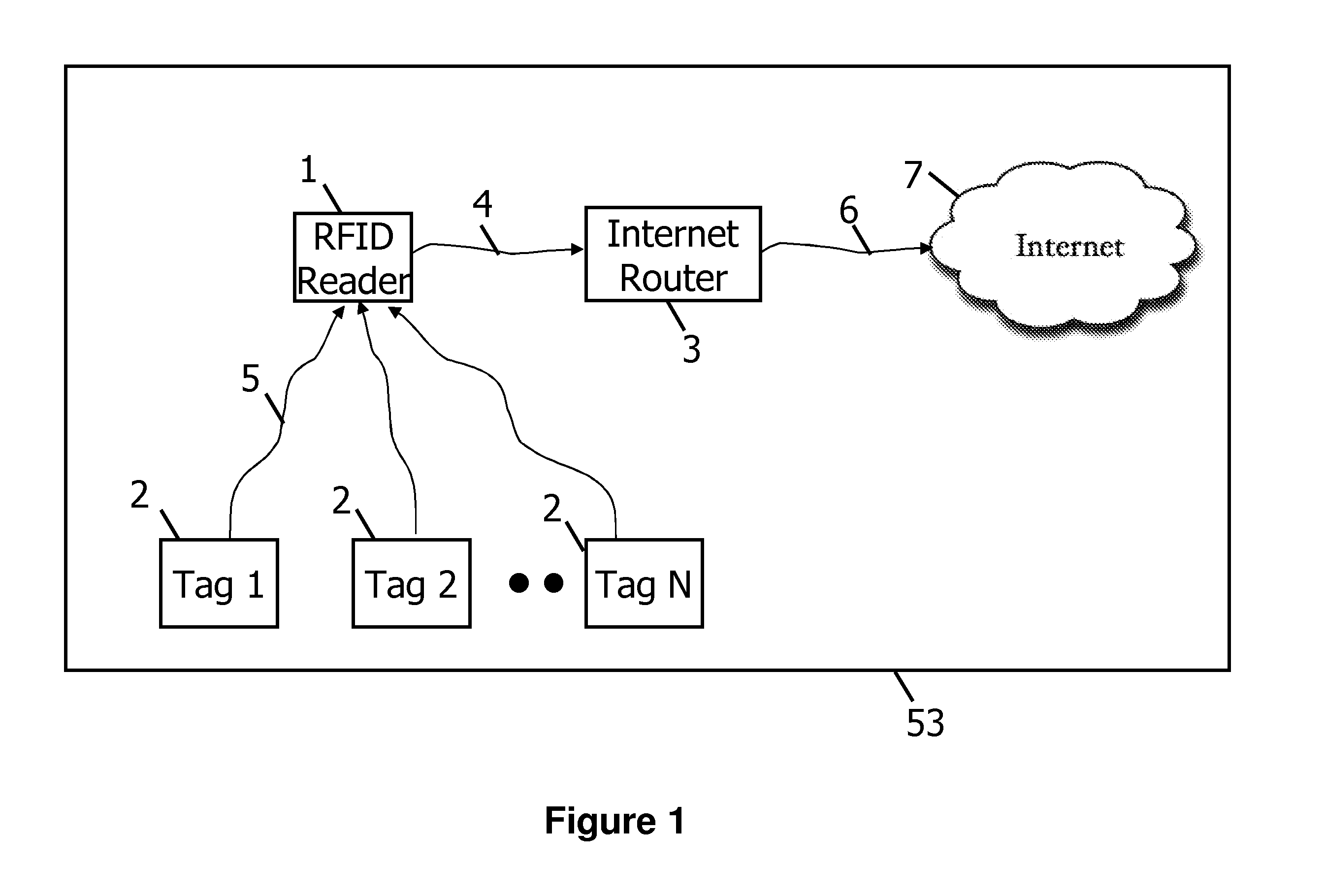
[0020]FIG. 1 is a schematic diagram of an RFID system 53 that embodies aspects of the present invention. The apparatus includes one or more radio frequency identification (RFID) tags 2, and o...


PUM


Abstract

A method and apparatus for building a long range RFID system is disclosed. A new signaling structure called Block Pseudo Noise is described that allows for more computationally efficient decoding. A novel approach to synchronize the RFID reader local oscillator with the RFID tag oscillator using an on board GPS receiver on the RFID tags and RFID reader is also disclosed. A novel positioning technique called Asynchronous Time Difference of Arrival used to located RFID tags is also disclosed.

Description

CROSS-REFERENCE[0001]This application claims priority to U.S. Application No. 61 / 273,660 filed on Aug. 7, 2009, “Wireless asset tracking system” the contents of which are hereby incorporated by reference in their entirety.TECHNICAL FIELD[0002]The Subject matter described herein relates generally to methods and apparatus for long range wireless radio frequency identification (RFID) devices. More particularly, but not exclusively, the subject matter described herein relates to algorithms used to extend the range of RFID tags, locate RFID tags and systems and methods for the use of GPS satellite signals for time and frequency synchronization of RFID tags.BACKGROUNDPrior Art[0003]Early work related to range extension in wireless communication and positioning networks can be found in US Application No. 20100039326, published on Feb. 18, 2010, “Variable Coherence Integration for the Location of Weak Signals,” the contents of which are hereby incorporated by reference in their entirety. In...

Claims


Application Information

Patent Timeline
IPC IPC(8): H04Q5/22
CPCG06K7/0008H04Q2213/13095G06K19/0723
Inventor WILD, BEN
Owner RING LLC
Learn More