
Method for producing a sensor including a core-shell nanostructure

a nano-structure, sensor technology, applied in the field of sensors, can solve the problems of insufficiently sensitive nano-chemical sensors, unstudied or reported, etc., and achieve the effect of improving the sensitivity of the sensor, reducing the cost and time taken to produce the sensor, and excellent sensitivity

Active Publication Date: 2017-09-26
INHA UNIV RES & BUSINESS FOUNDATION
View PDF10 Cites 7 Cited by
  • Summary
  • Abstract
  • Description
  • Claims
  • Application Information

AI Technical Summary

Benefits of technology

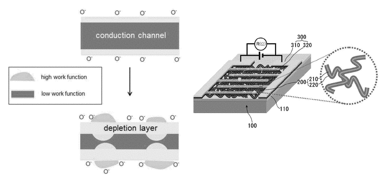
The sensor achieves high sensitivity in detecting infinitesimal amounts of reducing gases, preventing hazards by maximizing the modulation of the conduction channel and utilizing a p-n junction and work function difference for improved gas sensing performance.

Problems solved by technology

Especially, since a reducing gas including various volatile organic compounds (VOC) is considerably harmful to the human body, and has a high risk of explosion, in case that a high sensitive nano chemical sensor is developed and thus, it is possible to preemptively detect an infinitesimal amount of a reducing gas, the high sensitive nano chemical sensor is expected to be very useful.
However, a high sensitive nano chemical sensor, which is sufficiently sensitive to the reducing gas, was not studied or reported before.

Method used


Image

  • Method for producing a sensor including a core-shell nanostructure
  • Method for producing a sensor including a core-shell nanostructure
  • Method for producing a sensor including a core-shell nanostructure

Examples


specific example 1

Preparing of CuO—ZnO Core-Shell Nanowire

[0309]A CuO—ZnO core-shell nanowire was prepared through a novel two-step process, and through this, a gas sensor was prepared.

[0310]First, a CuO core nanowire was synthesized by using an electrospinning method, and then, a ZnO shell layer was deposited by using an ALD method.

[0311]Polyvinyl alcohol (PVA) having a molecular weight of 80,000 and copper acetate (CH2CO2)2Cu were used as precursor compounds for synthesizing the CuO core nanowire. For electrospinning, PVA beads were dissolved in diluted water to prepare 9 weight % of a PVA solution. After the PVA solution was stirred at a temperature of 70° C. for 4 hours, the PVA solution was mixed with a copper acetate solution, and the mixed solution was further stirred at a temperature of 70° C. for 6 hours. The viscous copper acetate / PVA solution was loaded inside a glass syringe provided with a 21-gauge stainless steel needle. Nanowires were uniformly electrospun on a SiO2 wafer disposed on a...

specific example 2

Preparing of SnO2—ZnO Core-Shell Nanowire 1

[0332]A SnO2—ZnO core-shell nanowire was prepared through a novel two-step process like Specific Example 1, and through this, a gas sensor was prepared.

[0333]First, a SnO2 core nanowire was synthesized by using an electrospinning method, and then, a ZnO shell layer was deposited by using an ALD method.

[0334]Polyvinyl pyrrolidone (PVP) having a molecular weight of 1,300,000 and tin chloride [SnO2.2H2O] were used as precursor compounds for synthesizing the SnO2 core nanowire. For electrospinning, 1.75 g of tin chloride was mixed with a dimethylformamide (DMF) and ethanol solvent having a volume ratio of 1:1, and the resultant mixture was stirred at a temperature of 70° C. for 30 minutes. PVD beads were dissolved in a solution containing the precursors to prepare 8 weight % of a solution, and the solution ws additionally stirred for 8 hours. The viscous tin chloride / PVA solution is loaded inside a glass syringe provided with a 21-gauge stainle...


PUM

PropertyMeasurementUnit
thicknessaaaaaaaaaa
thicknessaaaaaaaaaa
diameteraaaaaaaaaa

Abstract

The present invention relates to a sensor including a core-shell nanostructure, and more particularly, to a sensor including: a base material; a sensing part including a core-shell nanostructure that has a core including a first metal oxide and a shell including a second metal oxide formed on the core; and two electrode layers spaced from each other on the sensing part.

Description

CROSS-REFERENCE TO RELATED APPLICATIONS[0001]This application is a continuation of International Application No. PCT / KR2013 / 001198, filed Feb. 15, 2013, which PCT application designates the United States and claims the benefit of Korean Application No. 10-2012-0084858, filed Aug. 2, 2012, and Korean Application No. 10-2013-0015359, filed Feb. 13, 2013, the entire disclosures of each of which are incorporated by reference herein.TECHNICAL FIELD[0002]The present disclosure invention relates to an sensor including: a base material; a sensing part including a core-shell nanostructure that has a core including a first metal oxide formed on the base material, and a shell including a second metal oxide formed on the core; and two electrode layers spaced apart from each other on the sensing part.BACKGROUND ART[0003]A chemical sensor is a sensor using, as a sensing principle, a density change of conduction electrons on a surface of a semiconductor material, which is caused by a chemical inte...

Claims


Application Information

Patent Timeline
Patent Type & Authority Patents(United States)
IPC IPC(8): G01N27/414H01L29/225H01L29/06H01L21/02B82Y15/00B82Y40/00H01L29/24G01N27/12
CPCG01N27/4146B82Y15/00B82Y40/00H01L21/02554H01L21/02603H01L29/0669H01L29/0673H01L29/24G01N27/127H01L29/225
Inventor KIM, SANG SUBCHOI, SUN-WOOKATOCH, AKASH
Owner INHA UNIV RES & BUSINESS FOUNDATION
Learn More