
Method for measuring the distance between a workpiece and a machining head of a laser machining apparatus

a technology of laser machining and distance measurement, which is applied in the direction of laser beam welding apparatus, manufacturing tools, instruments, etc., can solve the problems of difficult to precisely position the focal spot and not deliver reliable measurement results under all conditions, and achieve reliable and precise manner

Active Publication Date: 2017-09-26
PRECITEC OPTRONIK GMBH
View PDF11 Cites 0 Cited by
  • Summary
  • Abstract
  • Description
  • Claims
  • Application Information

AI Technical Summary

Benefits of technology

[0011]It is an object of the invention to specify a method for measuring the distance between a workpiece and a machining head of a laser machining apparatus, by which the distances can be measured in a particularly reliable and precise manner. It is additionally an object of the invention to specify a machining head that is suitable for executing the method.
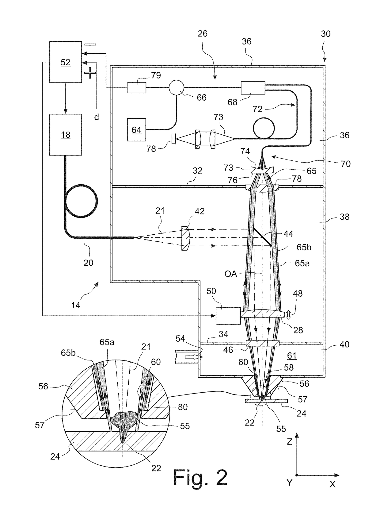
[0023]In the case of one embodiment, the measuring beam is reflected at a reflective face that is realized on an inner face of a housing of the machining head that delimits the interior. The measuring beam thereby passes twice through the interior, with the result that a greater measuring accuracy is achieved. Moreover, in this way, sensitive optical components required for evaluating the measuring beam can be arranged at a greater distance from the end of the machining head that faces towards the workpiece and that is subjected to high thermal and mechanical loads.
[0024]In particular, it is a possibility for the measuring beam that is incident upon the reflective face to be reflected back into itself. In this way, the measuring beam can enter the interior and, after being reflected at the reflective face, emerge again from the interior via the same optics.
[0025]It is particularly advantageous if the reflective face is in immediate proximity to the opening. It is thereby ensured that even pressure fluctuations in direct proximity to the opening are taken into account by the measuring beam.
[0035]It may additionally be advantageous if a plurality of object beams are directed, independently of each other, on to differing regions of the workpiece. It can thereby be ensured, e.g. in the case of laser cutting, that at least one measurement point is located outside of the kerf. Moreover, with three or more measurement points, an inclination of the workpiece can be captured.
[0036]If at least one of the plurality of object beams is incident upon the workpiece coaxially with the laser radiation, the distance of the machining site from the machining head can be measured. In this way, in the case of cutting work, the current cut-in depth can be measured at the start of the cutting operation. As soon as the parting operation has been completed, the machining head can be moved relative to the workpiece, in order to produce a cutting edge.

Problems solved by technology

In the use of such laser machining apparatus, it is difficult to position the focal spot in an exact manner on the surface of the workpieces to be machined, the diameter of which focal spot is usually between 100 μm and 500 μm in the case of welding work, and may be 20 μm and less in the case of cutting work.
It has been found, however, that the measurement of distance by means of coherence tomographs, which is highly promising per se, does not deliver reliable measurement results under all conditions.

Method used


Image

  • Method for measuring the distance between a workpiece and a machining head of a laser machining apparatus
  • Method for measuring the distance between a workpiece and a machining head of a laser machining apparatus
  • Method for measuring the distance between a workpiece and a machining head of a laser machining apparatus

Examples


Embodiment Construction

[0059]1. Structure of the Laser Machining Apparatus

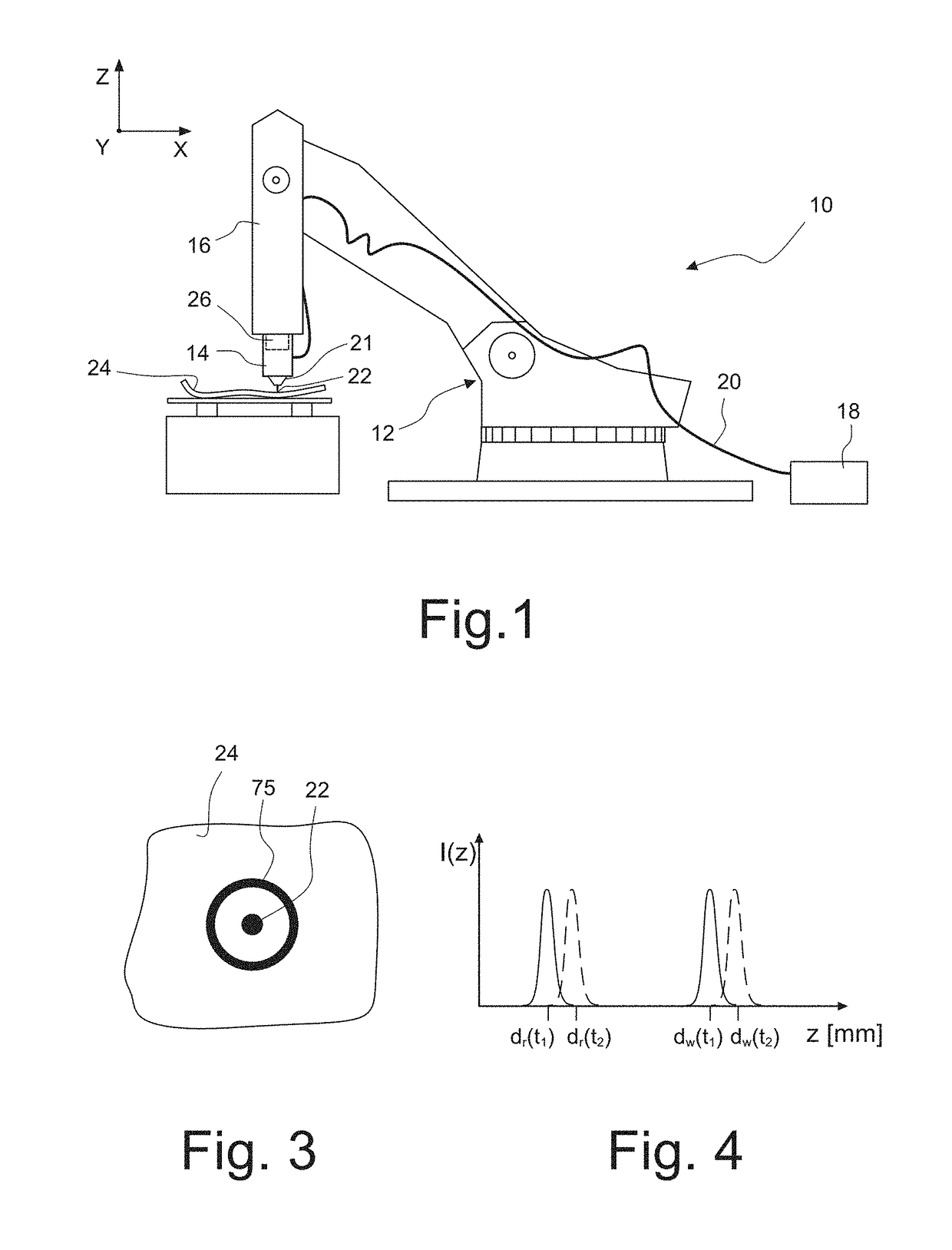
[0060]FIG. 1, in a schematic representation, shows a laser machining apparatus 10, having a robot 12, and having a machining head 14 according to the invention, which is attached to a movable arm 16 of the robot 12.

[0061]The laser machining apparatus 10 additionally includes a laser beam source 18, which, in the embodiment represented, is realized as a disc laser. Such lasers generate laser radiation having a wavelength in the order of magnitude of 1 μm. By means of an optical fibre 20, laser radiation 21 generated by the laser beam source 18 is supplied to the machining head 14, and is focussed by the latter in a focal spot 22 for the purpose of machining a workpiece 24.

[0062]The workpiece 24, which, in the embodiment represented, is to be cut by the laser machining apparatus 10, is a curved panel of a fibre-reinforced plastic. These are composed of an organic matrix, which is reinforced either with carbon fibres (carbon-fibre plas...


PUM

PropertyMeasurementUnit
diameteraaaaaaaaaa
diameteraaaaaaaaaa
diameteraaaaaaaaaa

Abstract

According to a method for measuring the distance between a workpiece and a machining head of a laser machining apparatus, a machining head is provided, which has a housing that has an interior and an opening for emergence of the laser radiation from the machining head. The laser radiation is directed on to the workpiece, after it has passed through the interior and the opening. An object beam is directed on to the workpiece by a light source of an optical coherence tomograph in such a manner that the object beam passes through the interior and the opening before being incident upon the workpiece. In addition to the object beam, a measuring beam passes through the interior. The measuring beam is used to compensate falsifications of the measured distance that have been caused by pressure fluctuations in the interior. The measuring beam in this case may be reflected at a reflective face that is formed on an inner face of an outlet nozzle that comprises the opening, which inner face delimits the interior.

Description

BACKGROUND OF THE INVENTION[0001]1. Field of the Invention[0002]The invention relates to a method for measuring the distance between a workpiece and a machining head of a laser machining apparatus by means of which workpieces can be welded, cut or otherwise machined.[0003]2. Description of the Prior Art[0004]Laser machining apparatus usually comprise a laser radiation source, which may be, for example, a CO2 laser, a fibre laser or a disc laser. A laser machining apparatus additionally includes a machining head, which focuses the laser radiation, generated by the laser radiation source, in a focal spot, and a beam delivery means, which delivers the laser radiation, generated by the laser radiation source, to the machining head. The beam delivery means in this case may comprise optical fibres or other optical waveguides, and / or one or more deflecting mirrors having planar or curved faces. The machining head may be attached to a movable robot arm or to another positioning device that ...

Claims


Application Information

Patent Timeline
Patent Type & Authority Patents(United States)
IPC IPC(8): B23K26/08G01B9/02B23K26/04G01B11/14
CPCB23K26/0892B23K26/04B23K26/048B23K26/0884G01B9/02091G01B11/14G01B21/042
Inventor SCHOENLEBER, MARTINKOGEL-HOLLACHER, MARKUSBAUTZE, THIBAULT
Owner PRECITEC OPTRONIK GMBH
Learn More