
Method for controlling a printing press

a printing press and control technology, applied in the field of controlling the printing press, can solve the problems of affecting the quality of printing, the relatively abrupt transition of the vibratory motion between adjacent cylinders of the two subsystems, and the negative influence of vibratory motion on the print quality, so as to achieve convenient adjustment, high precision, and reliable and precise manner

Inactive Publication Date: 2005-03-29
HEIDELBERGER DRUCKMASCHINEN AG
View PDF18 Cites 3 Cited by
  • Summary
  • Abstract
  • Description
  • Claims
  • Application Information

AI Technical Summary

Benefits of technology

The method according to the present invention for controlling a drive of a first subsystem of a printing press which is, at least at some times, mechanically decoupled from a second subsystem of the printing press has the feature that a motion sequence is determined for the second subsystem in advance, the motion sequence being composed of a basic motion sequence and an additional motion sequence and used as a reference curve for controlling the drive of the first subsystem. This has the advantage that the motion sequences of the first and second subsystems can be very accurately synchronized or else be correlated in a different way. A synchronization of the two motion sequences takes place at least over time intervals or during periods in time. In spite of the mechanical decoupling of the two subsystems and the generally different vibration behaviors, this control of the drive of the first subsystem allows very accurate synchronization with the motion sequence of the second subsystem at all times.
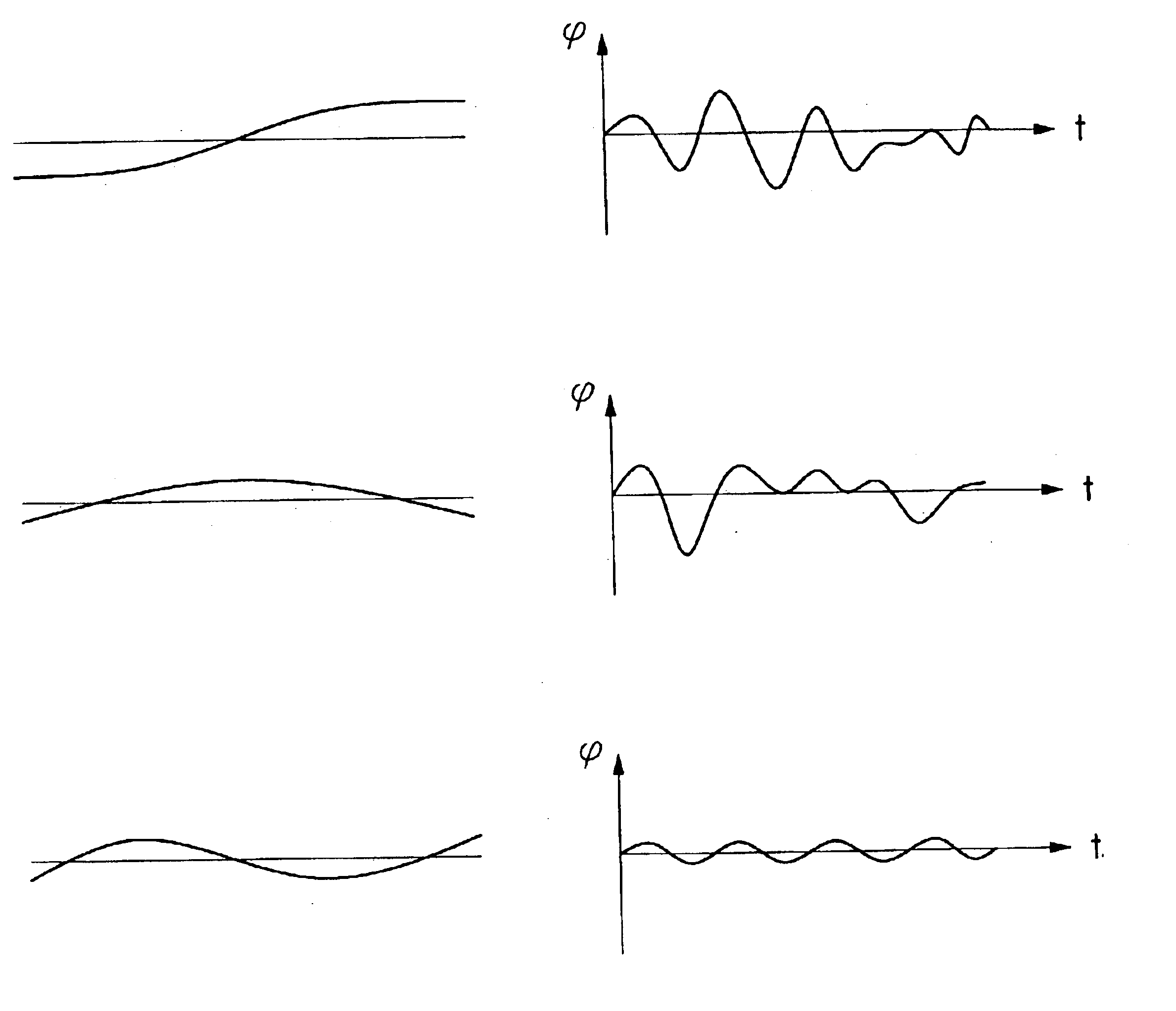
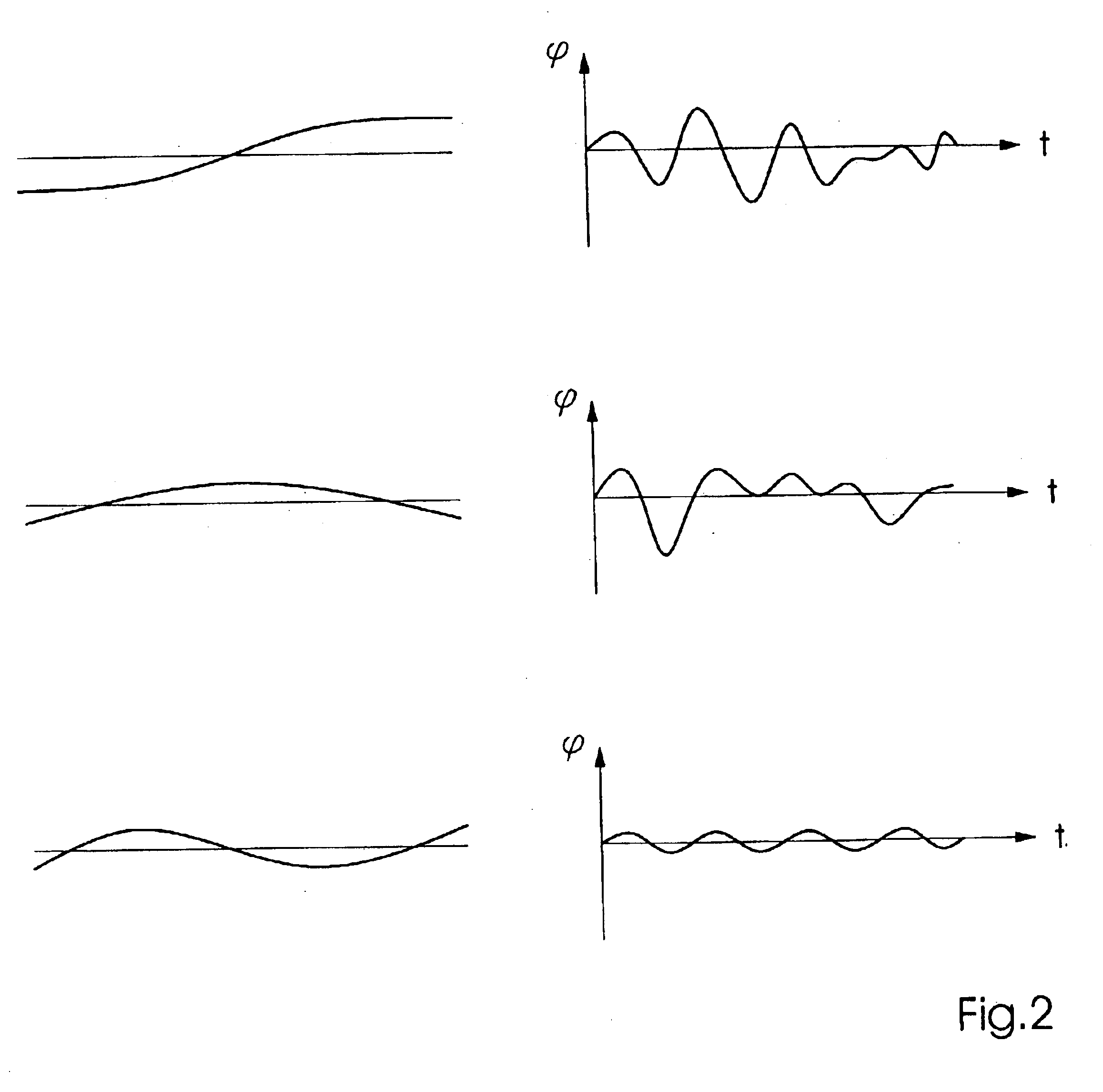
Since the complexity of the motion sequence of the second subsystem is essentially caused by the vibration behavior thereof, a systematic and expedient way of characterizing the motion sequence is to determine natural modes of vibrations (the spectrum or the basis of the natural modes) to a selectable order for the second subsystem in advance, and to determine characteristics of vibrational amplitudes which are associated with the respective natural modes and form the basis on which the motion sequence can be reconstructed. In other words, the additional motion sequence superimposed on the basic motion sequence can be represented by a breakdown into natural modes of vibrations to an order required to achieve a selectable precision. Moreover, this has the advantage that the particular desired accuracy can be easily adjusted through the selection of the order that is still to be considered. It is clear that the natural modes of vibrations can be the natural modes of vibrations of the overall system, of the first or second subsystems, or even of a part of the subsystems. In other words, the spectrum or the basis on which a breakdown is carried out is selectable. A preferred selection of the natural modes will be determined, inter alia, by the convergence behavior of the representation of the additional motion sequence in natural modes.
In the preferred embodiment, the reference curve is modified as a function of the current operating condition of the printing press. In this context, the reference curve can be modified as a function of a current value of a characteristic operating condition, such as the temperature, of the printing press. It is also possible for the reference curve to be alternatively or additionally modified as a function of the current motion sequence of the second subsystem. A further variant is to modify the reference curve as a function of an average value for the current motion sequence of the second subsystem. Taking into account the current operating condition advantageously allows the drive to be controlled in a very reliable and precise manner. The method automatically adapts to the respective prevailing operating situation and is also able to automatically process changes in the printing press to a certain degree.
The drive of the first subsystem is preferably controlled in such a manner that the first subsystem simulates the reference curve, i.e., that the first subsystem moves in sync with the second subsystem. To this end, the reference curve can be fed as a setpoint signal to a regulating device which controls the drive of the first subsystem. In this context, a very beneficial effect is obtained when the setpoint signal precedes the current motion sequence of the second subsystem by a selectable phase difference. The precedence in time gained through the phase difference can be used to carry out the input from the reference curve almost without delay and with high precision and, in fact, even if the reference curve exhibits high dynamics. With regard to this, it is also an advantage if the regulating device contains a precontrol and a controller which are each fed with the setpoint signal, a coarse control of the drive of the first subsystem being carried out by the precontrol and a fine control of the drive of the first subsystem being carried out by the controller. In other words, the precontrol allows high dynamics and the controller permits high precision. In order to form a closed-loop control circuit, the controller can be fed with an actual-value signal characterizing the current motion sequence of the first subsystem.

Problems solved by technology

The mechanical coupling of the individual cylinders results in a vibratory system having a very complex structure so that a complicated pattern of vibratory motions is superimposed on the rotary motions of the cylinders.
The vibratory motions can have a negative influence on the print quality.
This can result in a relatively abrupt transition in the vibratory motion between adjacent cylinders of the two subsystems.
However, the strongly varying excitation torques, which are frequently to be observed in printing presses and which place very high demands on the dynamics of the measures provided, generally create problems.

Method used


Image

  • Method for controlling a printing press
  • Method for controlling a printing press
  • Method for controlling a printing press

Examples


Embodiment Construction

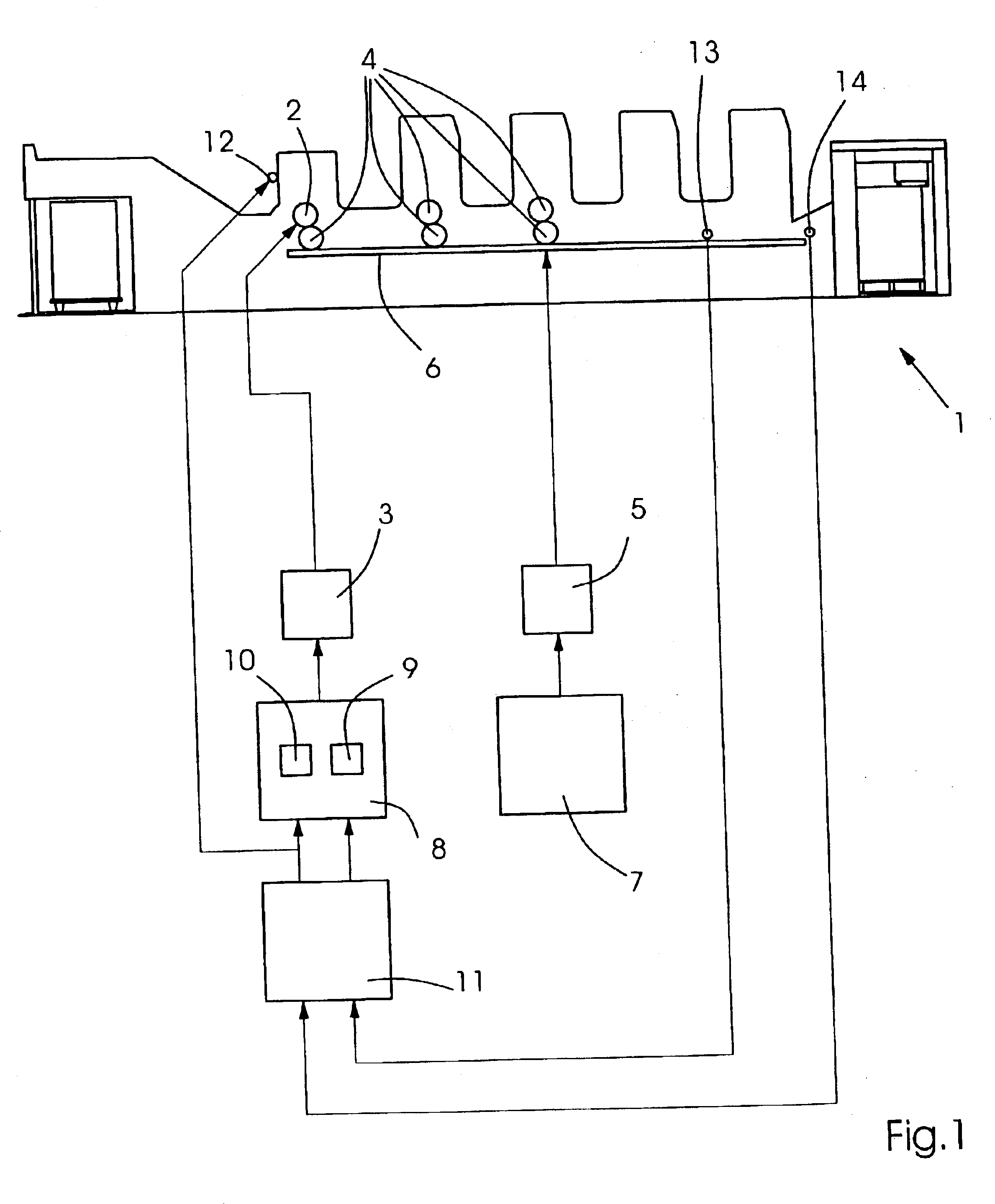
FIG. 1 is a schematic representation of a printing press 1, including components which are relevant in the context of the method according to the present invention. Printing press 1 is composed of two subsystems which each feature a separate drive device. The first subsystem has a cylinder 2 which is driven by a first drive motor 3. Depending on the form of construction, it is also possible for drive motor 3 to drive a plurality of cylinders 2. The second subsystem contains a number of cylinders 4 which are mechanically coupled to each other and driven together by a second drive motor 5. The mechanical coupling of cylinders 4 of the second subsystem is symbolically indicated by a line 6 and can be implemented, for example, by a gear train. The gear train, on one hand, allows all cylinders 4 of the second subsystem to be driven by the same drive motor 5 and, on the other hand, ensures that the rotary motions of cylinders 4 of the second subsystem are performed in sync with each other...


PUM


Abstract

A method for controlling a drive (3) of a first subsystem of a printing press (1) which is mechanically decoupled from a second subsystem of the printing press (1). In the method, a motion sequence is determined for the second subsystem in advance, the motion sequence being used as a reference curve for controlling the drive (3) of the first subsystem.

Description

Priority to German Patent Application No. 102 02 255.0, filed Jan. 21, 2002 and hereby incorporated by reference herein, is claimed.BACKGROUND INFORMATIONThe present invention relates to a method for controlling a printing press.In a printing press, a plurality of cylinders are set into rotation during the printing operation. Since the printing of a printing substrate takes place in a continuous process during which the printing substrate sequentially passes the individual cylinders, the rotary motions of the cylinders have to be synchronized. This is generally also true for cylinders which do not come directly in contact with the printing substrate, such as the ink transfer cylinders. The synchronization of the individual cylinders is often accomplished by providing a single drive motor which, via mechanical coupling means, such as shafts, gear wheels, chains and couplings, drives all cylinders to be driven.The mechanical coupling of the individual cylinders results in a vibratory ...

Claims


Application Information

Patent Timeline
Patent Type & Authority Patents(United States)
IPC IPC(8): B41F13/004B41J29/08B41F33/00
CPCB41F13/0045
Inventor KNOPF, ERICSCHREIBER, STEFAN
Owner HEIDELBERGER DRUCKMASCHINEN AG
Learn More