
Dual voltage supply

a voltage supply and dual-current technology, applied in the field of electronic integrated circuits, can solve the problems of slow rise times from the output buffer, slow response to changes in loading, and poor bandwidth of the regulator

Active Publication Date: 2017-09-19
PSEMI CORP
View PDF3 Cites 6 Cited by
  • Summary
  • Abstract
  • Description
  • Claims
  • Application Information

AI Technical Summary

Problems solved by technology

In low power applications, this regulator generally has fairly poor bandwidth and slow response to changes in loading.
These large capacitors may be large while still allowing voltage droop problems under extreme loading which may lead to slow rise times from the output buffer.

Method used


Image

  • Dual voltage supply
  • Dual voltage supply
  • Dual voltage supply

Examples


Embodiment Construction

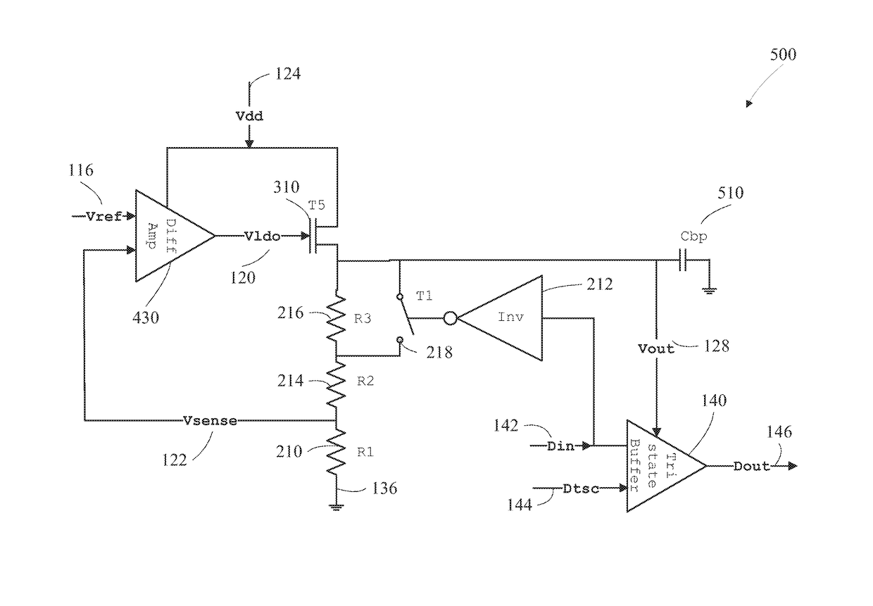
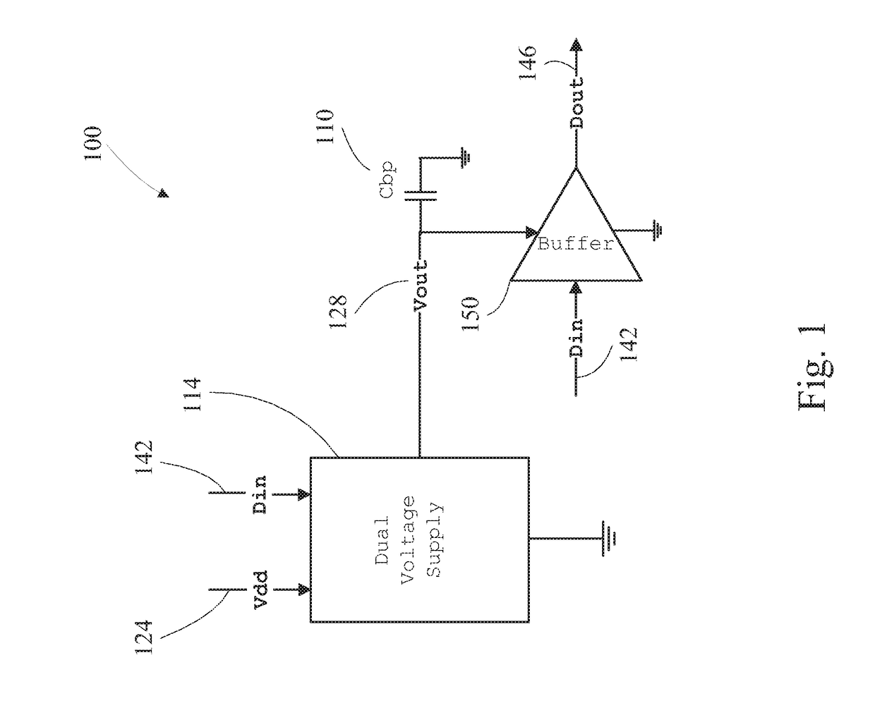
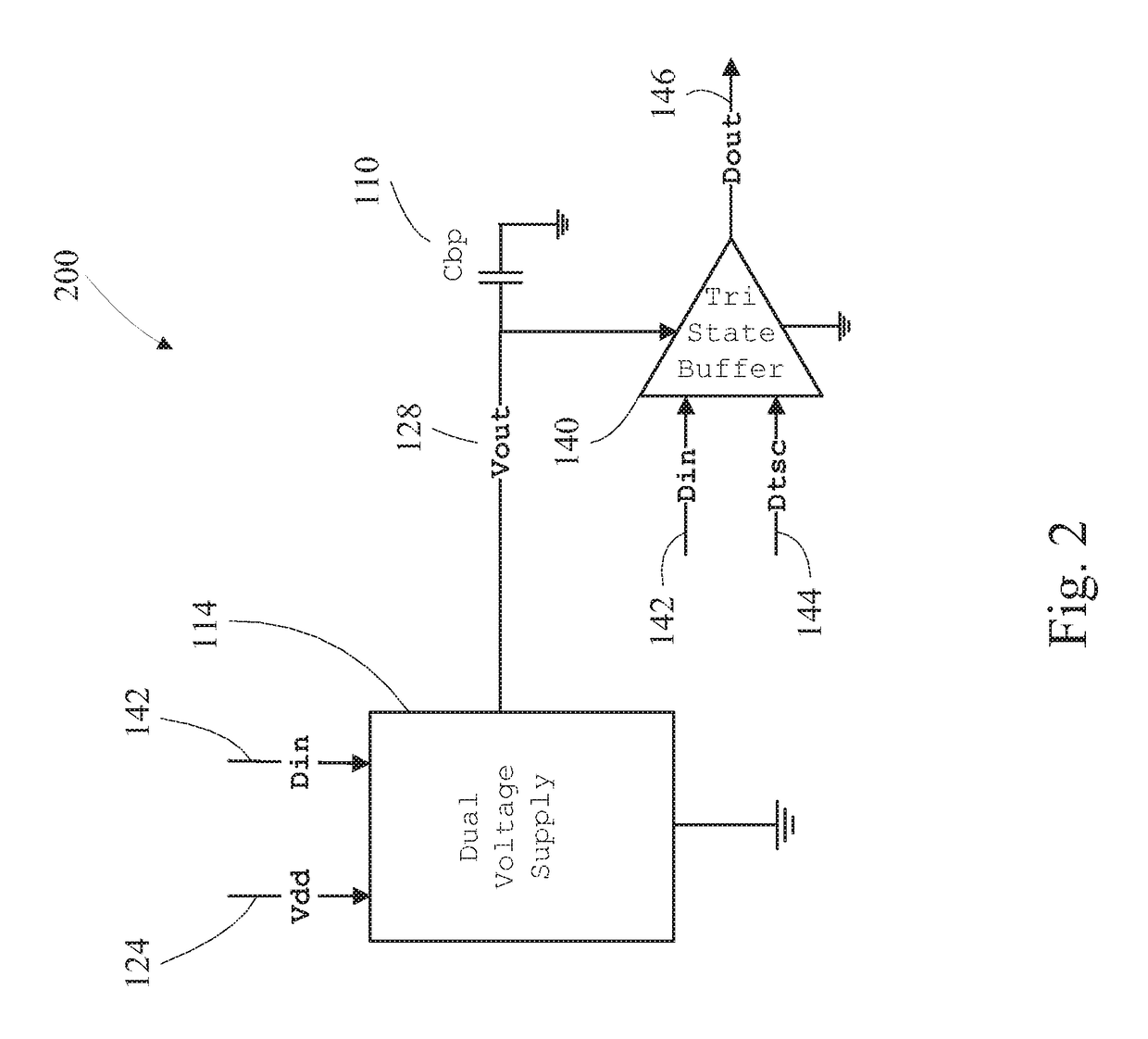
[0028]A circuit is disclosed which supplies output buffers with their own supply regulator. The regulator has two voltage output settings: nominal (1.8V) and high (2V). When the output buffer is tasked with outputting a low (e.g. 0V), the regulator is set to a high voltage pre-charge state. When the output buffer is set to a high state and the load capacitance has to be charged to 1.8V, the charge on the storage capacitor above the voltage that is to be utilized may be dissipated to create crisp rising edges because the output supply does not dip below the target output high voltage. Tuning of storage capacitors to an output buffer load capacitance results in sharper waveforms. In initial simulations with the disclosed circuit having a 15 pF load on the output buffer, only 100 pF of storage capacitance is required to generate sharp waveforms. Without the pre-charge function, the storage capacitor may have to be four times larger for similar results.

[0029]FIG. 1 depicts an overview o...


PUM


Abstract

A system, comprising a dual voltage supply configured to receive a logic state input voltage and configured to output an output voltage, wherein the dual voltage supply is configured to output a nominal voltage at a high state of the logic state input voltage and the dual voltage supply is configured to output a high voltage at a low state of the logic state input voltage, a pre-charge capacitor is configured to receive the output voltage of the dual voltage supply and an output buffer has an output buffer power input is coupled to the pre-charge capacitor and configured to receive the output voltage of the dual voltage supply, an output buffer signal input is configured to receive the logic state input voltage and an output buffer output is configured to output a digital output signal.

Description

BACKGROUND[0001](1) Technical Field[0002]The present disclosure is widely applicable to electronic integrated circuits (ICs). Specifically a dual voltage supply driving a output buffer.[0003](2) Background[0004]When a digital supply is not available to power a digital output buffer, a supply is created from whatever supplies exist on-chip. In low power applications, this regulator generally has fairly poor bandwidth and slow response to changes in loading. Thus it is common to use large storage capacitors to stabilize the output voltage. These large capacitors may be large while still allowing voltage droop problems under extreme loading which may lead to slow rise times from the output buffer.[0005]Therefore, regulating the supply voltage of a buffer by using a dual voltage supply may provide a solution to the slow rise times from the output buffer while reducing size.SUMMARY OF THE INVENTION[0006]In one embodiment, a system, comprising a dual voltage supply configured to receive a...

Claims


Application Information

Patent Timeline
Patent Type & Authority Patents(United States)
IPC IPC(8): H03K19/094H01C1/16H03K19/00H03F3/45
CPCH03K19/0002H01C1/16H03F3/45H03F1/0211
Inventor ENGLEKIRK, ROBERT MARK
Owner PSEMI CORP
Learn More