
Drive apparatus

a technology of drive apparatus and drive shaft, which is applied in the direction of electric vehicles, electric vehicles, dynamo-electric machines, etc., can solve the problems of low efficiency, large size and weight of traditional drive apparatus, etc., and achieve safer and reliable operation, increase the power density of electric bike systems, and save and more stable effects

Active Publication Date: 2017-09-12
JOHNSON ELECTRIC SA
View PDF8 Cites 1 Cited by
  • Summary
  • Abstract
  • Description
  • Claims
  • Application Information

AI Technical Summary

Benefits of technology

[0005]Thus, there is a desire for a drive apparatus for an electric bike, which has a light weight and high power density and is capable of stable operation.
[0019]In the drive apparatus for the electric bike as described above, multiple small motors simultaneously drive the internal gears via idle gears, which in turn rotates the housing body. This makes the entire operation system safer and more stable. By mounting multiple small motors in the gear system, the power density of the electric bike system can be increased. In addition, multiple small motors are connected in series and share one controller, which provides a safer and more reliable operation system with lower cost. In addition, peaks of the cogging torque of the motors can be staggered, which can reduce the cogging torque of the entire drive apparatus and hence reduce the zero-load resistance of the electric bike.

Problems solved by technology

However, the traditional drive apparatus has a large size and weight and a low efficiency, which is against the trend of electric bikes toward light weight, high power and increased efficiency to extend the range per charge.

Method used


Image

  • Drive apparatus
  • Drive apparatus
  • Drive apparatus

Examples


Embodiment Construction

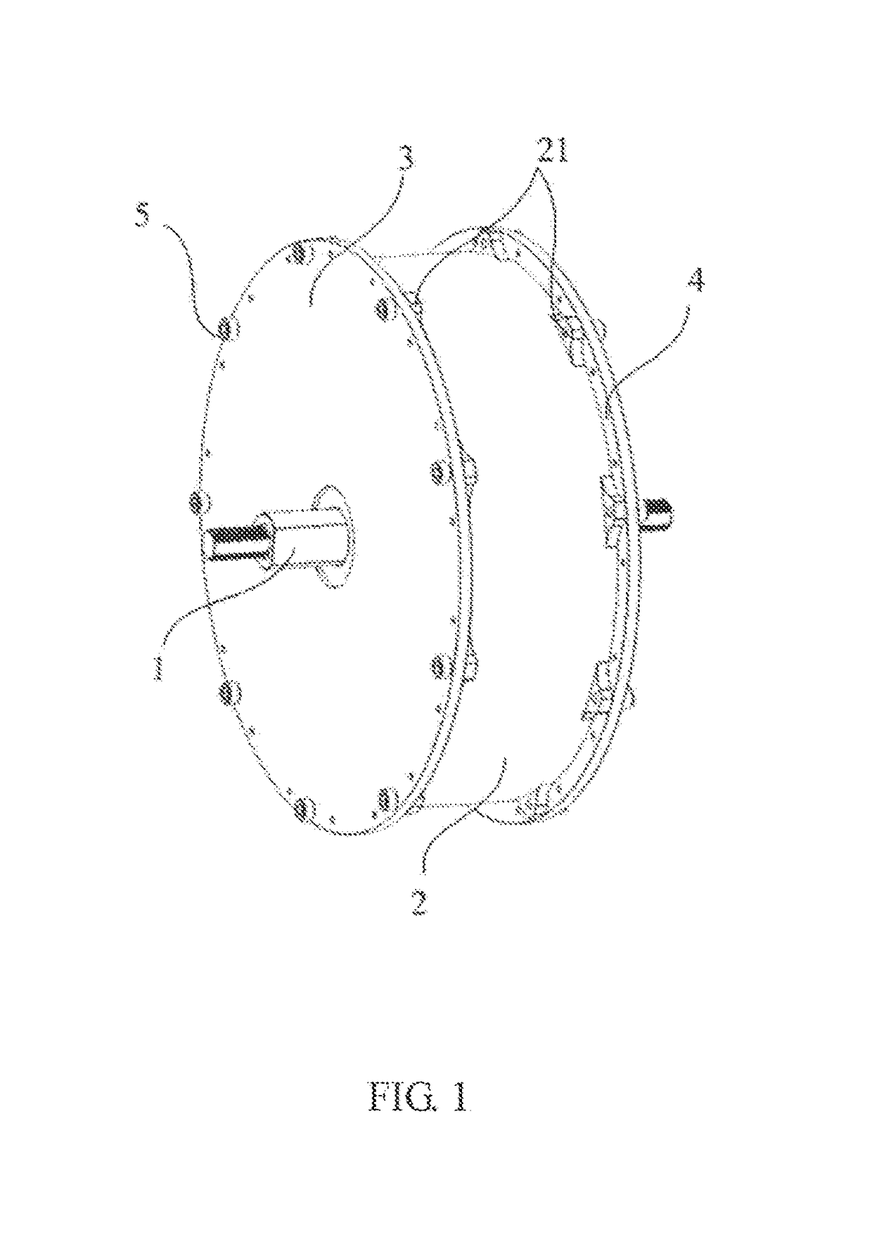
[0029]FIG. 1 illustrates a drive apparatus for an electric bike according to the preferred embodiment of the present invention. The drive apparatus includes a main shaft 1, and an outer housing rotatably mounted around the main shaft 1. The outer housing includes a cylindrical hollow housing body 2 and end caps 3, 4 enclosing opposite ends of the housing body 2. Outer flanges at the opposite ends of the housing body 2 are formed with multiple protrusions 21. The end caps 3, 4 are fixed to the protrusions 21 with fasteners 5. In one embodiment, the fasteners 5 are screws. In use the main shaft is fixed to a frame of the bike so that it can not turn. The housing body forms the hub of the rear wheel of the bike and thus rotates about the main shaft.

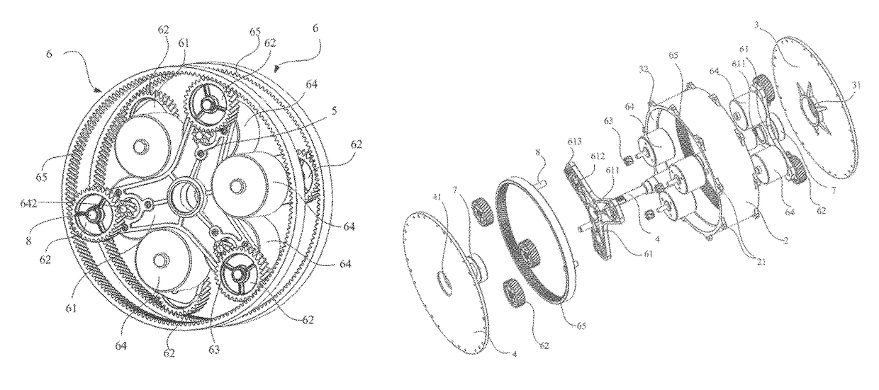
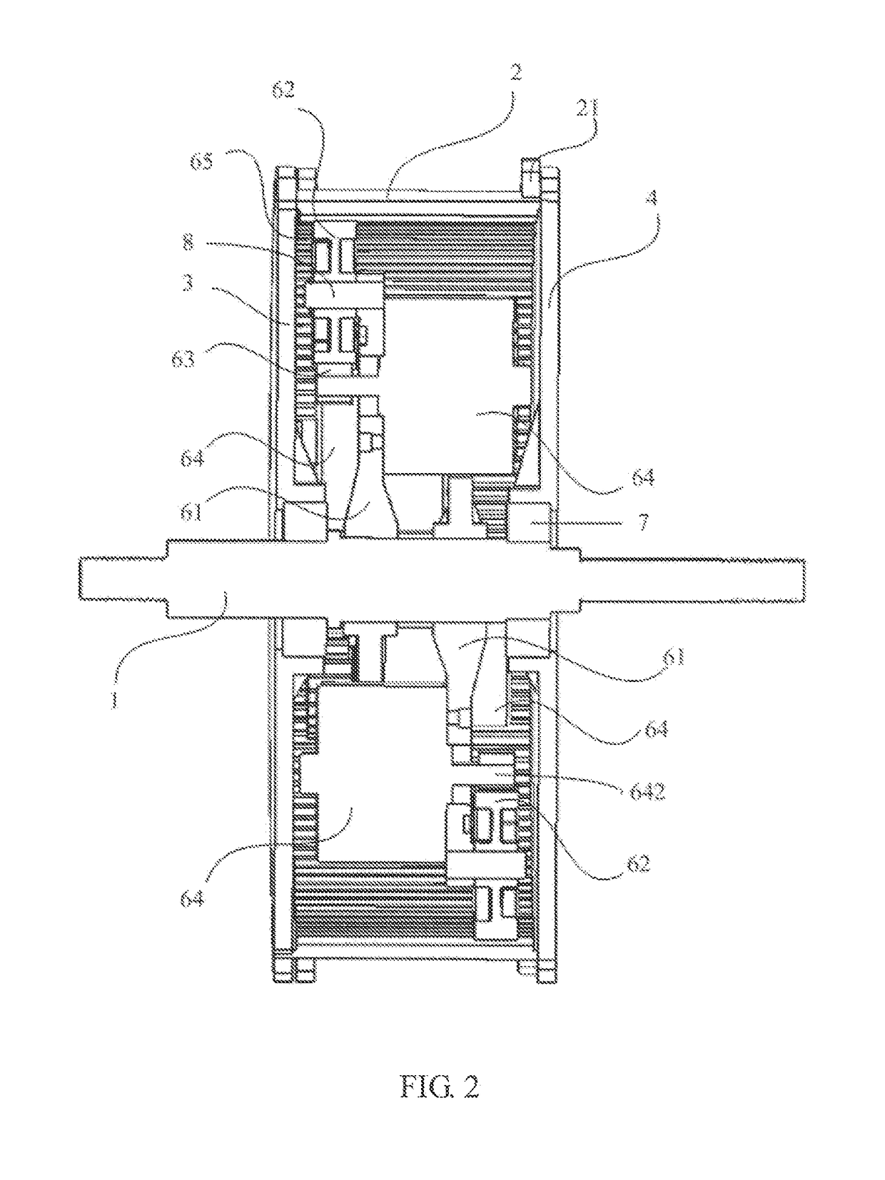
[0030]Referring to FIG. 2 to FIG. 4, the drive apparatus comprises a plurality of motors arranged in at least two groups of motor, referred to hereafter as motor units 6, disposed in the housing body 2. At least one internal ring gear 65 is ...


PUM


Abstract

A drive apparatus for an electric bike includes a hollow housing body, an internal ring gear fixed to the housing body, and a main shaft. At least two motor units are mounted in the housing body. Each motor unit includes a support bracket and a number of motors mounted on the support bracket. Each motor drives the internal gear through a transmission mechanism to rotate the housing body about the main shaft. The motors share one controller. Peaks of the motor cogging torque can be staggered.

Description

CROSS REFERENCE TO RELATED APPLICATIONS[0001]This non-provisional patent application claims priority under 35 U.S.C. §119(a) from Patent Application No. 201410306671.0 filed in The People's Republic of China on Jun. 30, 2014, the entire contents of which are hereby incorporated by reference.FIELD OF THE INVENTION[0002]This invention relates to a drive apparatus for an electric bike having multiple electric motors.BACKGROUND OF THE INVENTION[0003]Electric bikes use electric power as a primary or auxiliary power system, with manual power being an alternate system in some cases. The electric power system has at least one electric motor, a controller, storage battery, an input device and a display. In recent years, as an environment-friendly and energy-saving transportation tool, electric bikes have grown in popularity. As a key component of the electric bikes, the power system's configuration and quality often determine the overall performance of the electric bikes.[0004]Current power ...

Claims


Application Information

Patent Timeline
Patent Type & Authority Patents(United States)
IPC IPC(8): H02K7/116B62M6/65H02K7/14B62M6/60H02K16/00
CPCH02K7/116B62M6/60B62M6/65H02K7/14H02K16/00Y02T10/641Y02T10/64
Inventor LI, YUECHAI, JIETA, JING NINGDING, HONG YUZHANG, TAOZHOU, CHUI YOU
Owner JOHNSON ELECTRIC SA
Learn More