Apparatus and method for recovering and regenerating a refrigerant from an A/C plant

a technology of apparatus and refrigerant, which is applied in the field of apparatus and method for recovering and regenerating refrigerant from an a/c plant, can solve the problems of unavoidable loss of refrigerant in vapour phase, serious damage to things or people, environmental damage,

Active Publication Date: 2017-09-12
SNAP ON CLIMATE SOLUTIONS SRL
View PDF11 Cites 4 Cited by
  • Summary
  • Abstract
  • Description
  • Claims
  • Application Information

AI Technical Summary

Benefits of technology

[0016]It is then a feature of the present invention to provide a device capable of purging air present in the regenerated refrigerant in a precise way, limiting to the minimum the loss of refrigerant and improving in the meantime the degree of purity of the regenerated refrigerant, in order to meet the regulations currently in force, which define a more restrictive degree of purity and maximum admissible loss of refrigerant into the environment.
[0029]Effusion is the process, governed by the above described equation, by means of which the gas molecules cross a thin calibrated hole from a container to another container where the pressure is lower. In particular, for a mixture of air (Mm(air)=28, 84 g / mol) and HFO1234yf (Mm(HFO1234yf)=114, 06=g / mol) it is obtained that the speed of air effusion is about double than the refrigerant; this makes it possible to exploit in an effective way the effusion for purging more air than vapour of refrigerant.
[0033]Advantageously, a plurality of separation chambers is provided adjacent to each other and separated by said selective passage means. This way, using one or more chambers in series at progressively lower pressures connected by holes of small diameter or alternatively, by porous dividing walls, with effusion of the mixture through the chambers and then purge from the last chamber of the air mixture into the environment, it is possible to obtain an ideal purging of sole air. This technique can be applied to any mixture of gas with the variable that this process is the more effective the more the molecular masses of the two gas are different from each other.
[0065]This way, when charging the air conditioning system, it is possible to transfer the refrigerant in liquid phase until it reaches said predetermined minimum threshold value. Beyond said value, it is possible to stop charging the refrigerant in liquid phase and to let a small amount of refrigerant in gaseous phase to flow towards the collector and the connection ducts, in such a way that the gas entrains the refrigerant in liquid phase remained in the connection ducts between the recovery and regeneration apparatus and the air conditioning system, pushing it completely into the air conditioning system. So, it is assured that all the refrigerant that has left the storage container, and that has been measured reading the loss of weight of the storage container, except from liquid and gaseous fractions that can be determined, has reached the air conditioning system. In other words, this particular technical solution allows testing and correlating the amount of refrigerant in liquid phase released by the reservoir to that present in the air conditioning system, having completely removed the refrigerant in liquid phase present in the connection ducts.
[0072]Advantageously, the first charging duct can provide a suction mouth close to the bottom of the storage container, in order to ensure a suction of the sole liquid phase of the refrigerant, and said second charging duct can provide a discharge mouth from said storage container in a top position of said storage container, in order to ensure a suction of the sole gaseous phase of the refrigerant. The position of the suction mouth and the discharge mouth of the gaseous phase ensures that there are not accidental flows of gas in the duct for the liquid or of liquid in the duct for the gas.
[0074]In particular, the second charging duct can provide a means for pumping refrigerant in gaseous phase from a reservoir. Even this alternative solution provides re-feeding refrigerant in gaseous phase, for avoiding the above described drawbacks.

Problems solved by technology

The purging step has, however, the drawback of causing unavoidably the loss of refrigerant in vapour phase, which is dragged out with air.
Considering that such treatment is carried out on a very high number of air conditioning systems per day, it can be understood that this produces a high accumulation of the refrigerant in the environment, causing environmental damages.
Furthermore, the cumulated discharge of refrigerant leads to not negligible economical damages due to the refrigerant cost, which is remarkably grown with a new type of refrigerant, called HFO 1234yf.
The discharge in the environment of refrigerant causes also safety problems, since the refrigerant HFO 1234yf is highly inflammable, and an excessive cumulated discharge in the environment can generate an atmosphere that can explode or burn causing very serious damages to things or people.
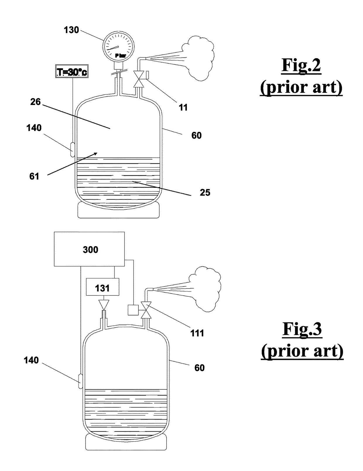
By purging air this way, it is apparent that the loss of refrigerant cannot be controlled, owing to the discharge of the vapour entrained with air in the gaseous phase of the storage container.
The methods described above have the drawbacks of discharging amounts of vapour of the refrigerant entrained with air.
If an attempt is made to reduce the loss of refrigerant, for example by stopping the discharge with a control on the loss by weight of the refrigerant, there is the opposite drawback to purge not completely the air present in the refrigerant.
However, this solution, can be acceptable for a refrigerating system, but cannot be used in a refrigerant regeneration system, since it would not ensure a suitable purification of the refrigerant without having waste of the same and polluting the environment.

Method used


Image

  • Apparatus and method for recovering and regenerating a refrigerant from an A/C plant
  • Apparatus and method for recovering and regenerating a refrigerant from an A/C plant
  • Apparatus and method for recovering and regenerating a refrigerant from an A/C plant

Examples


Embodiment Construction

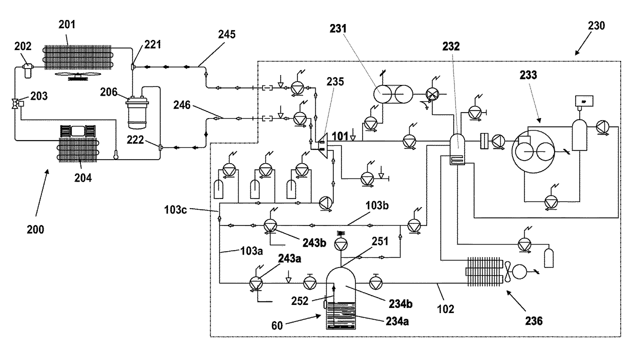
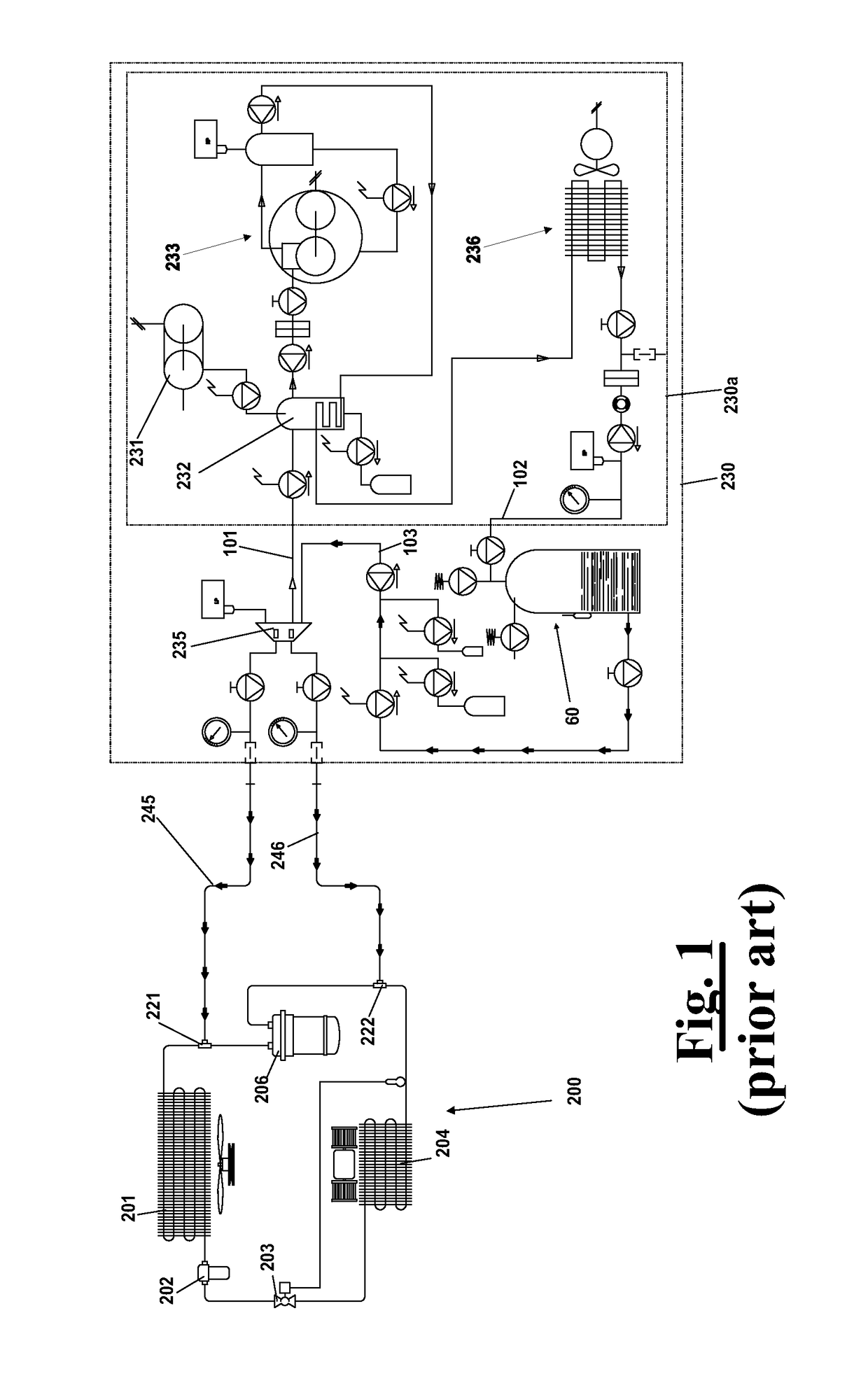
[0091]With reference to FIG. 1, an apparatus 230 is shown, according to the prior art, which is adapted to recover the refrigerant from an air conditioning system 200 by connection means as flexible ducts 245, 246 respectively connected to high pressure connector 221 and low pressure connector 222 of the air conditioning system 200. The latter comprises, as well known, a condenser 201, a filter 202, a calibrated hole 203, an evaporator 204, a storage container 205 and a compressor 206. The operation of recovering the refrigerant, through the ducts 245 and 246, is carried out mainly in liquid phase by the high pressure connector 221 and in gaseous phase by the low pressure connector 222.

[0092]Owing to the work of machine 230, the refrigerant by suction through ducts 245 and 246 reaches, via a collector 235 and a feeding duct 101, a purification unit 230a, comprising an evaporator 232, a compressor 233 and a condenser 236. Then, the refrigerant condensed and purified after the regener...


PUM


Abstract

An apparatus for recovering refrigerant from an air conditioning system includes an evaporator arranged to receive the refrigerant from the air conditioning system and to separate it from impurities present in it, obtaining purified refrigerant, a compressor for circulating the purified refrigerant, a condenser, and a storage container arranged to contain the condensed refrigerant. The storage container defines a storage chamber arranged to contain a liquid phase of the refrigerant and a gaseous phase including a vapor component of the refrigerant and an air component. The apparatus also includes a measuring means configured to measure operating parameters of the refrigerant present in the storage chamber, purge device arranged at a purge opening configured to purge the gaseous phase present in the storage chamber responsive to the operating parameters, and at least one first separation chamber connected to the storage container.

Description

FIELD OF THE INVENTION[0001]The present invention relates to a method to purge air from a refrigerant in a recovery and depuration apparatus, which is applied for example to an air conditioning system of a car.[0002]Furthermore, the invention relates to an apparatus that implements said method.BACKGROUND OF THE INVENTION[0003]As well known, the refrigerant present in air conditioning systems, in particular those on board of vehicles such as cars, is periodically recovered and recycled for eliminating the impurities accumulated during the operation cycle. To this purpose, the refrigerant is purged from the air conditioning system by a recovery and regeneration apparatus as described in EP1367343A1.[0004]In these types of machines the refrigerant is subjected to a regeneration cycle in which it is depurated of the impurities in it present. Air is one of these impurities that has to be purged.[0005]Presently, the elimination of air, in machines like EP1367343A1, is done by opening purg...

Claims


Application Information

Patent Timeline
Patent Type & Authority Patents(United States)
IPC IPC(8): F25B43/04F25B45/00
CPCF25B43/043F25B45/00F25B2345/001F25B2345/002F25B2345/003F25B2400/121
Inventor SANHAJI, RAHHALI
Owner SNAP ON CLIMATE SOLUTIONS SRL
Why Eureka
Try Eureka