
Rigid foam

a rigid foam and foam technology, applied in the field of rigid foam, can solve the problems of degrading the physical properties of rigid foam, unsuitable for most applications, and internal scorching of foams, and achieve the effect of increasing flame retardan

Active Publication Date: 2017-08-29
BASF AG
View PDF18 Cites 3 Cited by
  • Summary
  • Abstract
  • Description
  • Claims
  • Application Information

AI Technical Summary

Benefits of technology

The present invention provides a rigid foam that has increased flame retardance. This foam is made by reacting an isocyanate component and an isocyanate-reactive component in the presence of a isocyanurate catalyst component and a carbodiimide catalyst component. The resulting foam has a fast rise time and a fast tack-free time, making it useful in a variety of applications. The method of making the foam involves spraying the components onto a surface and can be easily modified for different applications.

Problems solved by technology

It is well known in the art that when conventional rigid foams, particularly spray foams, are formed in thicknesses of greater than about 2 inches, such foams are subject to internal scorching due to high exotherm temperatures resulting from reactions of certain isocyanates and polyols during formation.
Internal scorching not only degrades the physical properties of the rigid foams, rendering them unsuitable for most applications, but also has the potential to cause other problems related to flammability.
For example, these conventional rigid foams are vulnerable to burning and smoking, all of which are undesirable.
Although halogenated flame retardants are inexpensive and are used to meet the California requirement, they have been linked to environmental concerns.

Method used


Image

  • Rigid foam
  • Rigid foam
  • Rigid foam

Examples


examples

[0065]A series of rigid foams (Foams 1-8) are formed according to the present invention. A series of comparative rigid foams (Comp Foams 1 and 2) are also formed but not according to this invention. The Comp Foams 1 and 2 are not formed using the carbodiimide catalyst component of this invention. The isocyanate-reactive component and the isocyanate component, along with the reaction conditions used to form the Foams 1-8 and the Comp Foams 1 and 2, and the resulting physical properties are set forth in Table 1 below.

[0066]

TABLE 1CompCompFoam 1Foam 2Foam 1Foam 2Foam 3Foam 4Foam 5Foam 6Foam 7Foam 8Isocyanate-Reactive ComponentPolyester66.6758.362.0257.757.756.2556.2556.2546.2846.28PolyolMannich Polyol—15.47—15.315.315.3715.3715.3715.3715.37Chain Extender12.53.0911.633333366Plasticizer————————55Polymerization1.671.551.551.51.51.491.491.491.491.49CatalystSilicone6.673.096.2332.982.982.9833SurfactantIsocyanurate8.335.157.75554.994.994.9955CatalystBlowing—2.06—2222222CatalystCarbodiimide——...


PUM

PropertyMeasurementUnit
Temperatureaaaaaaaaaa
Weightaaaaaaaaaa
Timeaaaaaaaaaa

Abstract

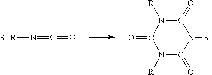
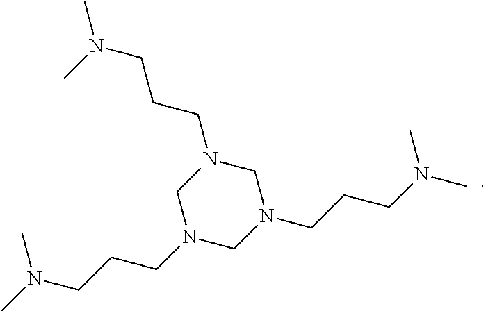
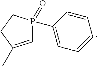
A rigid foam having increased flame retardance comprises the reaction product of an isocyanate component and an isocyanate-reactive component. The isocyanate component and an isocyanate-reactive component are reacted in the presence of an isocyanurate catalyst component and a carbodiimide catalyst component. The isocyanurate catalyst component comprises 1,3,5-tris(3-(dimethylamino)propyl)-hexahydro-s-triazine and the carbodiimide catalyst component comprises 3-methyl-1-phenyl-2-phospholene-1-oxide. A method of forming the rigid foam on a surface comprises the steps of providing the isocyanate component, providing the isocyanate-reactive component, providing the isocyanurate catalyst component, providing the carbodiimide catalyst component, and spraying the isocyanate component, isocyanate-reactive component, isocyanurate catalyst component, and carbodiimide catalyst component onto the surface to form the rigid foam on the surface.

Description

RELATED APPLICATIONS[0001]This application is the National Stage of International Patent Application No. PCT / US2014 / 011464, filed on Jan. 14, 2014, which claims priority to and all the advantages of U.S. Patent Application No. 61 / 752,483, filed on Jan. 15, 2013, the content of which is incorporated herein by reference.FIELD OF THE INVENTION[0002]The present invention generally relates to a rigid foam and, more specifically, to a rigid foam comprising the reaction product of an isocyanate component and an isocyanate-reactive component and to a method of forming the rigid foam.DESCRIPTION OF THE RELATED ART[0003]There is an increasing demand for better performing rigid foams that have particular flammability specifications and acceptable physical properties. It is well known in the art that when conventional rigid foams, particularly spray foams, are formed in thicknesses of greater than about 2 inches, such foams are subject to internal scorching due to high exotherm temperatures res...

Claims


Application Information

Patent Timeline
IPC IPC(8): C08G18/76C08G18/34C08G18/18C08G18/66C08G18/16C08G18/20C08G101/00
CPCC08G18/7685C08G18/161C08G18/1858C08G18/2036C08G18/34C08G18/6607C08G18/7614C08G2101/0025C08G2110/0025
Inventor JONES, CHARLES ELWOODWISHNESKI, TODD WILLIAM
Owner BASF AG
Learn More