Variable nozzle turbochargers

a turbocharger and variable nozzle technology, which is applied in the direction of liquid fuel engine components, pump components, non-positive displacement fluid engines, etc., can solve the problems of increasing the pressure loss of exhaust gas, performance degradation, and the inability to obtain the force required to press each member in one direction, so as to achieve the effect of biasing the unison ring

Active Publication Date: 2017-08-22
TOYOTA IND CORP +1
View PDF25 Cites 2 Cited by
  • Summary
  • Abstract
  • Description
  • Claims
  • Application Information

AI Technical Summary

Benefits of technology

[0011]As a result, it is possible to prevent rattling caused by a gap, backlash or the like between members connected together in a power transmission route. As compared with the related-art technique, this structure makes it possible to prevent an increase in pressure loss in the exhaust gas. Further, it prevents deterioration in performance without having to add any restrictions in terms of the design of the variable nozzles. According to the related-art technique, there is provided, for example, a structure for adjusting the pivot ratio of the variable nozzles, a structure for adjusting the positions of the pivots, or a structure for changing the configuration of the nozzle vanes.
[0013]As an opening degree detection unit, an operation amount detection unit may be provided for detecting the opening degree of the variable nozzles. This is possible to detect the opening degree of the variable nozzles with high precision.
[0016]According to another aspect of the invention, the spring member may be arranged on an area opposite the driving member for driving the unison ring. In this manner, the spring member can effectively bias the unison ring.

Problems solved by technology

In some cases, it is impossible to obtain the force required to press each member in one direction, e.g., the rotational force acting on the nozzle vanes so as to open the nozzle vanes with exhaust gas.
This, however, results in an increase in the pressure loss of the exhaust gas, thereby resulting in performance deterioration.
Thus, the springs cannot cope with the above problem.

Method used


Image

  • Variable nozzle turbochargers
  • Variable nozzle turbochargers
  • Variable nozzle turbochargers

Examples


Embodiment Construction

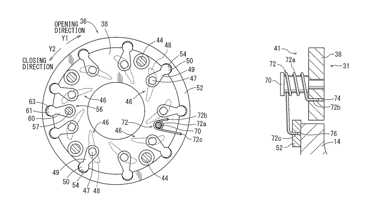
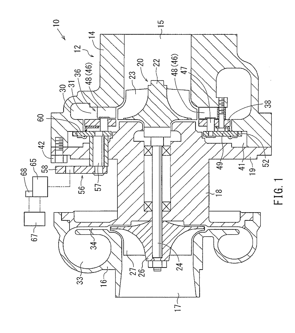
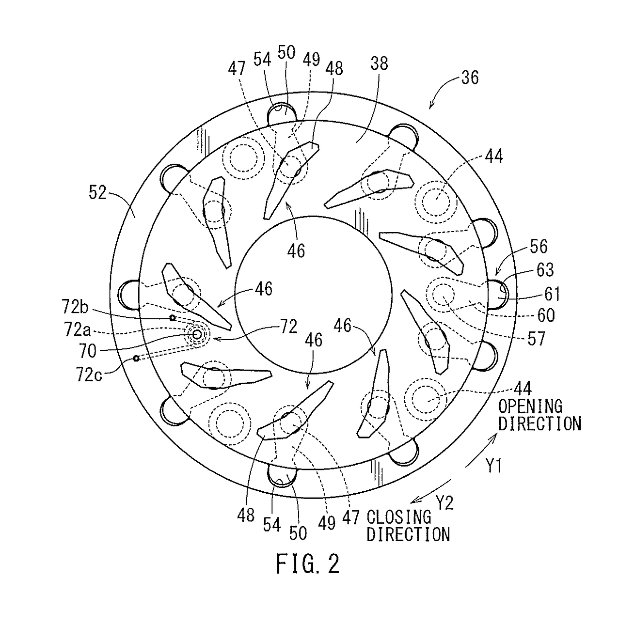
[0025]Each of the additional features and teachings disclosed above and below may be utilized separately or in conjunction with other features and teachings to provide improved variable nozzle turbochargers. Representative examples of the present invention, which utilize many of these additional features and teachings both separately and in conjunction with one another, will now be described in detail with reference to the attached drawings. This detailed description is merely intended to teach a person of ordinary skill in the art further details for practicing preferred aspects of the present teachings and is not intended to limit the scope of the invention. Only the claims define the scope of the claimed invention. Therefore, combinations of features and steps disclosed in the following detailed description may not be necessary to practice the invention in the broadest sense, and are instead taught merely to particularly describe representative examples of the invention. Moreover...


PUM


Abstract

Embodiments of the present invention may include a variable nozzle turbocharger having a variable nozzle mechanism for controlling a flow velocity of exhaust gas to a turbine wheel. The variable nozzle mechanism includes a plurality of variable nozzles, a unison ring and a biasing member. The variable nozzles each have a nozzle vane. The unison ring is configured to adjust a degree of opening of the variable nozzles through rotation of the unison ring. The biasing member biases the unison ring so as to open the variable nozzles.

Description

[0001]This application claims priority to Japanese patent application serial number 2013-104078, the contents of which are incorporated herein by reference.BACKGROUND OF THE INVENTION[0002]Field of the Invention[0003]Embodiments of the present invention relate to variable nozzle turbochargers.[0004]Description of the Related Art[0005]Japanese Utility Model Publication No. 63-115532 and Japanese Utility Model Publication No. 63-92036 disclose a variable nozzle turbocharger equipped with a variable nozzle mechanism. The variable nozzle mechanism adjusts the degree of opening of variable nozzles having nozzle vanes through rotation of a unison ring. Through this adjustment, the flow velocity of exhaust gas to a turbine wheel is controlled. In Japanese Utility Model Publication No. 63-115532, plate springs respectively biasing the variable nozzles in an axial direction of the unison ring are fixed to the unison ring. As a result, it is possible to prevent rattling caused by a gap betwee...

Claims


Application Information

Patent Timeline
Patent Type & Authority Patents(United States)
IPC IPC(8): F04D29/56F01D17/16
CPCF01D17/165F05D2220/40
Inventor UESUGI, TSUYOSHIIKEGAMI, HIROAKI
Owner TOYOTA IND CORP
Why Eureka
Try Eureka