Method for crimping a ring on an attachment rod using an automaton

a technology of a crimping machine and an attachment rod, which is applied in the field of crimping a ring on an attachment rod, can solve the problems of affecting the securing operation, so as to achieve advantageously prevent the risk of crimping in the absence of a ring

Active Publication Date: 2017-08-22
STELIA AEROSPACE
View PDF6 Cites 0 Cited by
  • Summary
  • Abstract
  • Description
  • Claims
  • Application Information

AI Technical Summary

Benefits of technology

[0010]a step of moving the crimping nose close to the attachment rod so as to prevent the removal of the ring from the attachment rod by the crimping nose;
[0013]By means of the method according to the invention, the ring is held by the clip on the attachment rod and released only when the crimping nose prevents its removal. Thus, the ring can be positioned on an attachment rod independently of its orientation. The disadvantages of the prior art are thus eliminated. In addition, the crimping nose advantageously fulfills a double function by enabling, on the one hand, the preventing of a removal of the ring, and, on the other hand, the crimping of the ring on the attachment rod.
[0014]Preferably, the method includes a preliminary step of alignment, by the movement clip, of the ring with the axis of the attachment rod. Thus, it is simple to position the attachment rod in the ring by a translation along the axis of the attachment rod. Preferably, the crimping nose is also aligned with the axis of the attachment rod.
[0017]According to a preferred aspect of the invention, the step of moving the movement clip and the step of moving the crimping nose are carried out simultaneously. Thus, the removal of the ring from the attachment rod is prevented from the time of the introduction. Moreover, a simultaneous movement makes it possible to prevent a relative movement between the movement clip and the crimping nose which are aligned relative to the axis of the attachment rod.
[0018]The automaton is preferably configured for detecting the presence of a ring in said movement clip. Thus, the risk of crimping in the absence of a ring is advantageously prevented.

Problems solved by technology

In practice, the pneumatic supply duct can have a length between 5 m and 25 m. Such a pneumatic duct is satisfactory for rivets or for a cylindrical ring, but it is not suitable for a flanged ring.
The pneumatic duct 13 is then blocked and a maintenance operation needs to be performed, which considerably slows the securing operations.
Finally, the flanged rings 1 can become damaged during the supplying, which presents another disadvantage.
In practice, it is difficult to ensure that the ring is positioned properly on the attachment rod.
Thus, a crimping step can occur in the absence of a ring, which can damage the attachment rod and / or the panel from which said rod extends protruding.
Finally, when the rod extends protruding from the top to the bottom, the ring is not stable on the attachment rod after blowing, which prevents any automated crimping with this type of attachment rod.

Method used


Image

  • Method for crimping a ring on an attachment rod using an automaton
  • Method for crimping a ring on an attachment rod using an automaton
  • Method for crimping a ring on an attachment rod using an automaton

Examples


Embodiment Construction

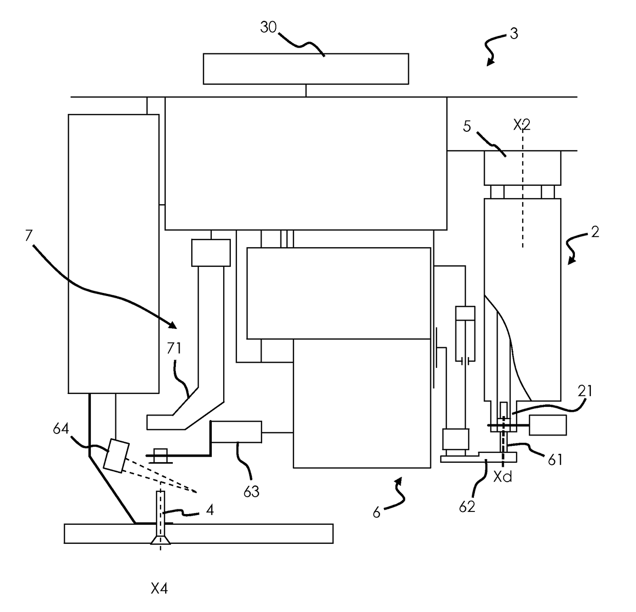
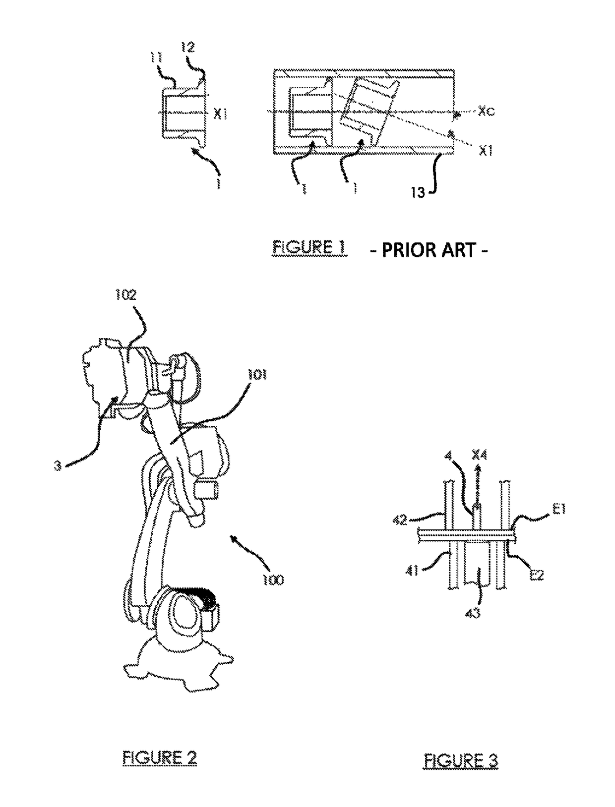
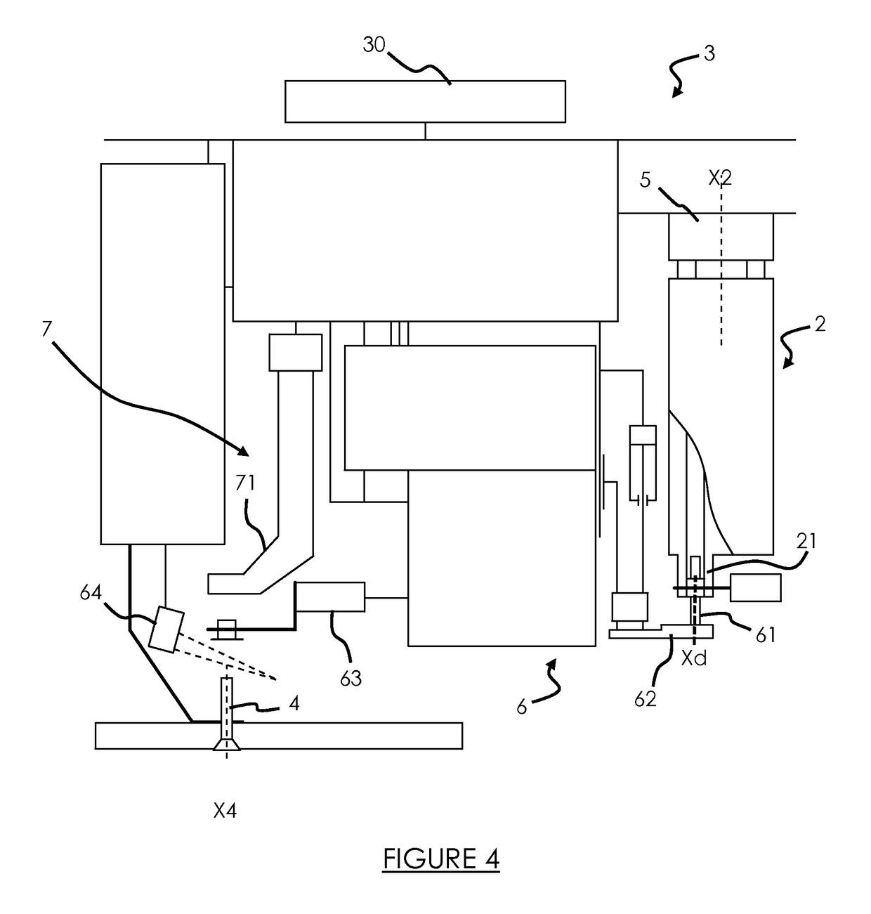
[0030]The invention will be presented in reference to FIG. 2 which shows a crimping automaton 100 comprising a preferably articulated mobile arm 101, which includes a head 102 on which a crimping module 3 is mounted. The automaton 100 makes it possible to crimp a ring on an attachment rod in order to form a riveted connection.

[0031]As an example, in reference to FIG. 3, two panels E1, E2 of an aircraft fuselage are represented, through which passes an attachment rod 4 which includes a protruding end extending longitudinally along a crimping axis X4 oriented vertically from the bottom to the top. In this example, the attachment rod 4 extends vertically; however, it could naturally extend in any direction.

[0032]In this example, the aeronautic panels E1, E2 are held against one another by stressing means 41, 42, while the attachment rod 4 is held by blocking means 43 known to the person skilled in the art or by another automaton.

[0033]Advantageously, the head 102 of the automaton 100 c...


PUM

PropertyMeasurementUnit
lengthaaaaaaaaaa
lengthaaaaaaaaaa
angleaaaaaaaaaa

Abstract

A method for crimping and a crimping tool, such as an automaton, to crimp a ring on an attachment rod extending along an axis of the attachment rod from a panel. The tool involves moving a movement clip of the automaton to grip the ring so that the attachment rod is introduced into the ring and moving a crimping nose of the automaton so as to prevent the removal of the ring from the attachment rod. Once crimped, the ring is released and the crimping nose is moved so as to ready the crimping tool for subsequent crimping of rings on attachment rods.

Description

GENERAL TECHNICAL FIELD AND PRIOR ART[0001]The present invention relates to the field of crimping of a ring on an attachment rod in order to form a riveted connection, in particular, in the aeronautics field.[0002]In order to secure two elements together, for example, two metal sheets, it is known to use an automaton to place rivets or the like in predetermined securing areas. The automaton can assume an inclined position, rotate or lengthen in order to reach different and various securing areas. Automaton is understood to mean a mechanical device capable of working in an automatic manner, that is to say without human intervention.[0003]The automaton is supplied with rivets or the like through a pneumatic supply duct in order to guide the rivets from a storage site (storage bowl, storage cassette, etc.) to the automaton. In practice, the pneumatic supply duct can have a length between 5 m and 25 m. Such a pneumatic duct is satisfactory for rivets or for a cylindrical ring, but it is...

Claims


Application Information

Patent Timeline
Patent Type & Authority Patents(United States)
IPC IPC(8): B21J15/02B21J15/10B21J15/32B21J15/14B21J15/28
CPCB21J15/022B21J15/10B21J15/32B21J15/142B21J15/285Y10T29/4978Y10T29/49778Y10T29/49943Y10T29/49956
Inventor HAUW, PHILIPPE
Owner STELIA AEROSPACE
Why Eureka
Try Eureka