
Fingerstall oximeter

a finger-clip oximeter and oximeter technology, applied in the field of finger-clip oximeters, can solve the problems of affecting the blood oxygen measurement result, reducing the measurement accuracy of the finger-clip oximeter, and complicated assembly/detachment procedure, so as to ensure the accuracy of measurement, avoid problems, and facilitate assembly/disassembly

Active Publication Date: 2017-08-08
BEIJING CHOICE ELECTRONICS TECH CO LTD
View PDF17 Cites 0 Cited by
  • Summary
  • Abstract
  • Description
  • Claims
  • Application Information

AI Technical Summary

Benefits of technology

The fingerstall oximeter provides accurate blood oxygen measurement with uniform pressure, reduces ambient light interference, and simplifies assembly and maintenance, improving measurement accuracy and industrial production efficiency.

Problems solved by technology

Therefore, the pressure at the finger tip near the twist spring is high, especially for fat fingers, such that feelings from the finger will be uncomfortable, and the blood flow would be blocked due to the high pressure on the finger, thus the blood oxygen measurement result will be affected.
Moreover, when the upper housing and the lower housing are separated for a certain angle during operation, the measurement result of the finger-clip oximeter is easily interfered by ambient light, leading to lower measurement accuracy of the finger-clip oximeter.
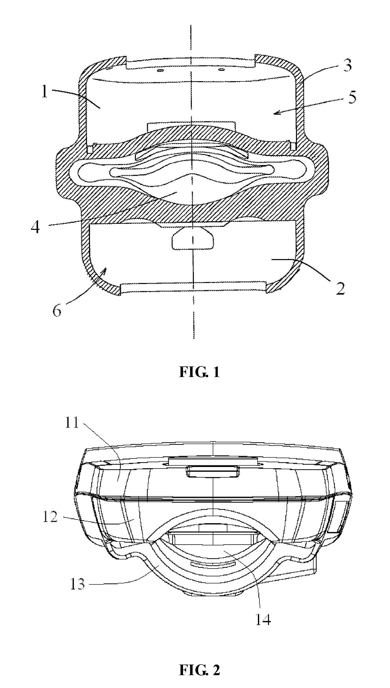
Thus when assembling the finger-type pulse and blood oxygen saturation measuring apparatus, firstly the detection device 1 and the power supply device 2 shall be assembled to corresponding carriers, and then be assembled with the soft case 3 together; on the other hand, when the finger-type pulse and blood oxygen saturation measuring apparatus needs maintain, the detection device 1, the power supply device 2 and the soft case 3 shall be separated firstly, then the detection device 1 and the power supply device 2 are detached from the respective carriers, leading to complicated assemble / deassemble procedure and inconvenience in assembling and maintain, and the poor firmness of the assembled apparatus.
Moreover, in the structure of the finger-type pulse and blood oxygen saturation measuring apparatus, since the detection device 1 and the power supply device 2 are disposed separately in the first / second accommodating portions, the thickness of the apparatus (i.e. the perpendicular distance from the upper surface of the first accommodating portion 5 to the lower surface of the second accommodating portion 6) is large and is not easy to carry.

Method used


Image

  • Fingerstall oximeter
  • Fingerstall oximeter
  • Fingerstall oximeter

Examples


Embodiment Construction

[0029]In order to make persons skilled in the art better understand the technical solutions of the present invention, the fingerstall oximeter provided by the present invention will be described in detail below in combination with the figures.

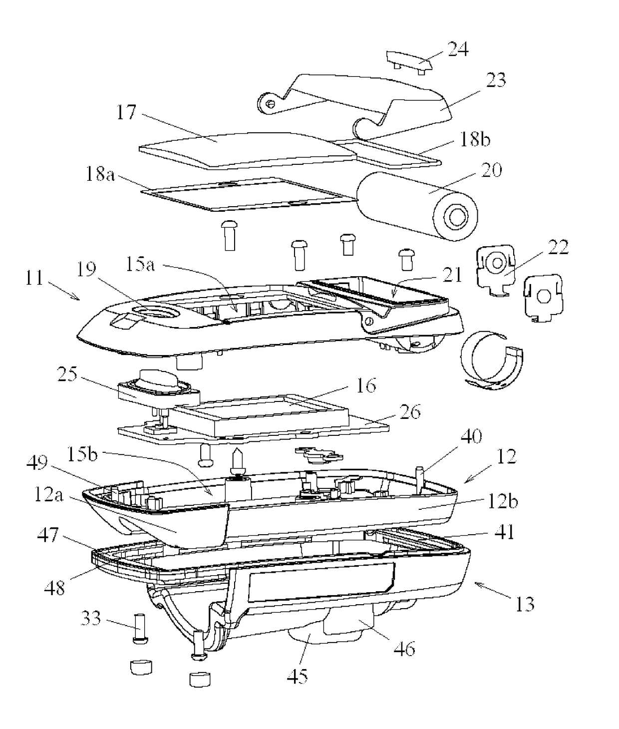
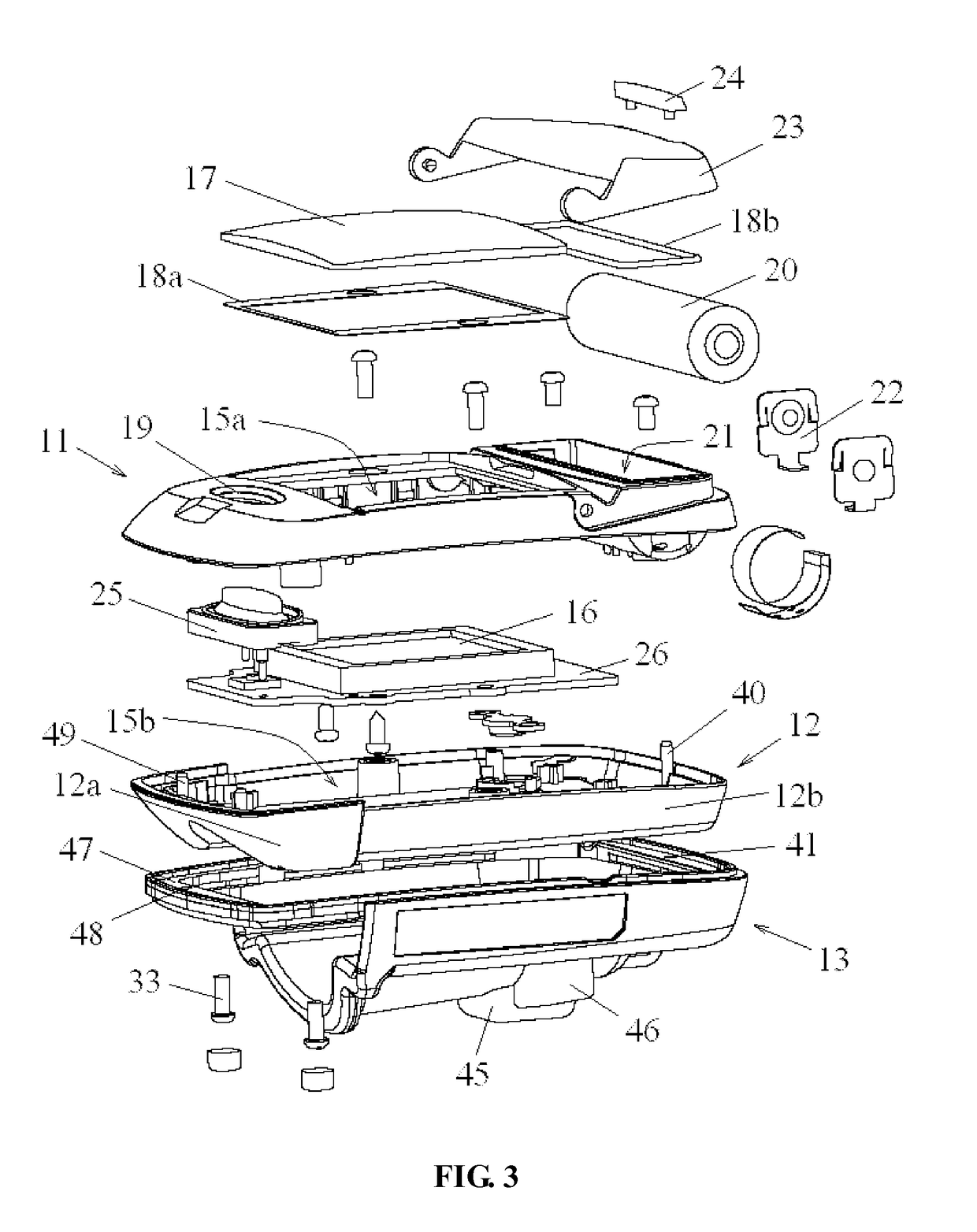
[0030]FIG. 2 is a schematic structural view of the fingerstall oximeter according to an embodiment of the present invention, and FIG. 3 is an exploded view of the fingerstall oximeter according to an embodiment of the present invention. Referring to FIGS. 2 and 3, the fingerstall oximeter comprises housings, a finger accommodating chamber 14 and a detection unit disposed in the housings, wherein the housings comprises an upper housing 11, a middle housing 12 and a lower housing 13, and the upper housing 11, the middle housing 12 and the lower housing 13 are connected in turn from top to bottom. A finger accommodating chamber 14 is formed between the opposed surfaces of the lower housing 13 and the middle housing 12, that is, the lower surface o...


PUM


Abstract

Disclosed is a fingerstall oximeter comprising an upper housing (11), a middle housing (12), a lower housing (13) and a detection unit. The upper housing (11), the middle housing (12) and the lower housing (13) are connected in turn. The lower housing (13) is made of silica gel, and a finger accommodating chamber (14) for accommodating a finger to be measured is formed between the opposed surfaces of the lower housing (13) and the middle housing (12). The fingerstall oximeter has high measurement accuracy and small volume, and is easy to disassemble and carry.

Description

CROSS-REFERENCE TO RELATED APPLICATIONS[0001]This application is the United States national phase of International Application No. PCT / CN2013 / 072263 filed Mar. 6, 2013, and claims priority to Chinese Patent Application No. 201210057401.1 filed Mar. 6, 2012, the disclosures of which are hereby incorporated in their entirety by reference.FIELD OF THE INVENTION[0002]The present invention relates to a technical field of blood oxygen measurement, and particularly relates to a fingerstall oximeter.BACKGROUND OF THE INVENTION[0003]Oximeter is a commonly used instrument for measuring pulse and degree of blood oxygen saturation. Typical oximeter includes finger-clip oximeter, desk-top oximeter and the like, among which the finger-clip oximeter is widely used for being easy to use and carry.[0004]Conventional finger-clip oximeter comprises an upper housing, a lower housing and a spring clip connecting the upper housing and the lower housing. A light emitting device and a light receiving devic...

Claims


Application Information

Patent Timeline
Patent Type & Authority Patents(United States)
IPC IPC(8): A61B5/1455A61B5/00A61B5/0205A61B5/024
CPCA61B5/6826A61B5/0205A61B5/14552A61B5/02427A61B5/6843
Inventor LIU, SHUHAIWANG, WEIHULI, ZUOBINWU, PENGWANG, WEI
Owner BEIJING CHOICE ELECTRONICS TECH CO LTD
Learn More