Liquid crystal display and display device

a liquid crystal display and display device technology, applied in the field of display technologies, can solve the problems of poor display effect or even unsuitability to be viewed, the inability to adjust only the luminance of the backlight source corresponding to this region, and the inability to adjust the luminance of the backlight source, so as to reduce the influence of ambient light on the display

Active Publication Date: 2020-05-26
BOE TECH GRP CO LTD
View PDF7 Cites 0 Cited by
  • Summary
  • Abstract
  • Description
  • Claims
  • Application Information

AI Technical Summary

Benefits of technology

[0008]Optionally, in the liquid crystal display provided by the embodiments of this disclosure, the backlight driving circuit is used for: comparing the light intensity in a position corresponding to each light emitting pixel of the backlight source in the display region with a first light intensity threshold; and if the light intensity in a position corresponding to the light emitting pixel is greater than the first light intensity threshold, increasing the luminance of the light emitting pixel in this corresponding position.
[0025]In the liquid crystal display and the display device provided by the embodiments of this disclosure, a plurality of photosensitive detectors are arranged in the frame region of the liquid crystal display panel. Light intensity distribution in the display region is estimated by a light intensity estimation module based on the light intensity detected by each photosensitive detector. Light intensity in a position corresponding to each light emitting pixel of the backlight source is determined based on the light intensity distribution in the display region estimated by the light intensity estimation module. Depending on the determined light intensity in a position corresponding to each light emitting pixel of the backlight source, luminance of the light emitting pixel in this corresponding position is controlled by a backlight driving circuit. In this way, when the ambient light irradiates onto the liquid crystal display panel with different intensities, even if the light intensities received by each zone of the display region are different, the backlight driving circuit can adjust luminance distribution of the backlight source based on the light intensity distribution of the display region, thereby reducing influence of the ambient light on the display effect.

Problems solved by technology

Most existing liquid crystal displays have a fixed luminance during display, and as a result, when the light intensity of an ambient light is high, the display effect is poor or even unsuitable to be viewed.
However, such a liquid crystal display may have a problem.
In this case, it is impossible to adjust only the luminance of the backlight source corresponding to this region.
Therefore, the image quality of the region irradiated by intense light in the screen will be severely affected, or even cannot be normally viewed.

Method used


Image

  • Liquid crystal display and display device
  • Liquid crystal display and display device
  • Liquid crystal display and display device

Examples


Embodiment Construction

[0029]Examples of the liquid crystal display and display device provided by the embodiments of this disclosure shall be described in detail with reference to the drawings.

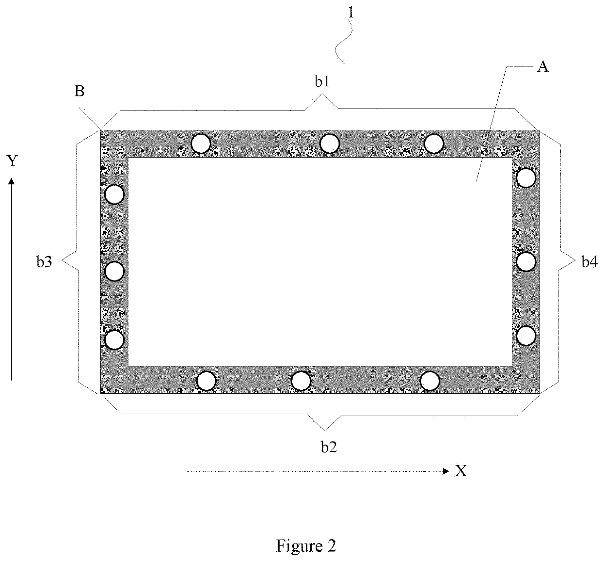
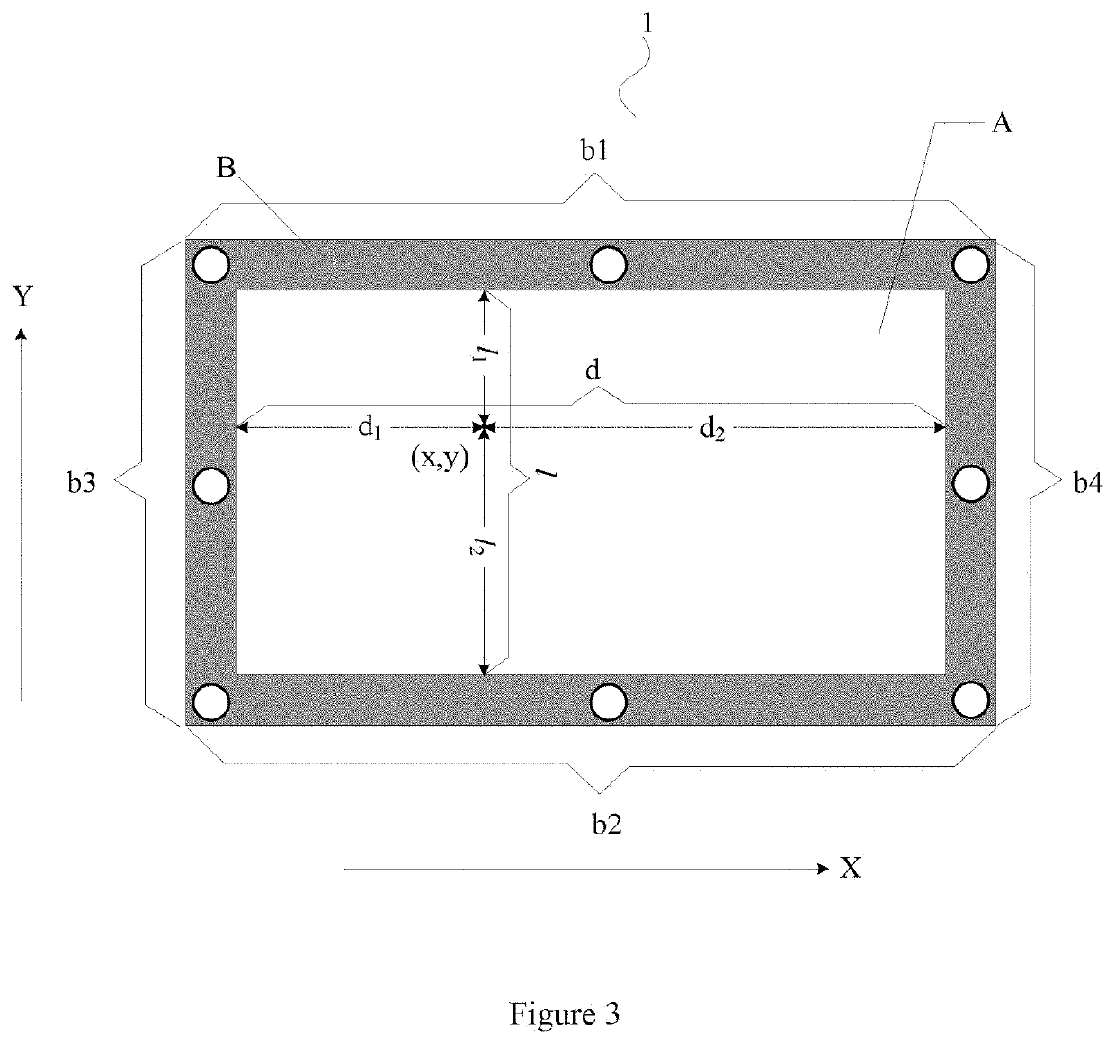
[0030]As shown in FIG. 1, the embodiments of this disclosure provide a liquid crystal display, comprising: a liquid crystal display panel 1, a backlight source 2 provided with a plurality of light emitting pixels arranged in a matrix, and a backlight driving circuit 3 for driving the backlight source 2 to emit light. The liquid crystal display panel 1 comprises a display region A and a frame region B surrounding the display region A. The liquid crystal display further comprises: a plurality of photosensitive detectors 01 located in the frame region B, and a light intensity estimation module 4 optionally connected between each photosensitive detector 01 and the backlight driving circuit 3. The photosensitive detectors 01 are used for detecting light intensities of the ambient light in positions where they are locate...


PUM

PropertyMeasurementUnit
light intensitiesaaaaaaaaaa
light intensity estimationaaaaaaaaaa
light intensityaaaaaaaaaa

Abstract

This disclosure relates to a liquid crystal display and a display device. A plurality of photosensitive detectors is arranged in the frame region of the liquid crystal display panel. Light intensity distribution in the display region is estimated by a light intensity estimation module based on the light intensity detected by each photosensitive detector. Light intensity in a position corresponding to each light emitting pixel of the backlight source is determined based on the light intensity distribution in the display region estimated by the light intensity estimation module. Depending on the determined light intensity in a position corresponding to each light emitting pixel of the backlight source, luminance of the light emitting pixel in this corresponding position is controlled by a backlight driving circuit.

Description

CROSS REFERENCE TO RELATED APPLICATIONS[0001]This application claims the benefit of Chinese patent application No. 201610028289.7 filed on Jan. 15, 2016, which is incorporated by reference in its entirety herein.FIELD[0002]This disclosure relates to the field of display technologies, and in particular to a liquid crystal display and a display device.BACKGROUND ART[0003]A liquid crystal display is a passive light emitting device and composed of a liquid crystal display panel and a backlight source, wherein the display luminance of the liquid crystal display panel is determined by the luminance of the backlight source. Most existing liquid crystal displays have a fixed luminance during display, and as a result, when the light intensity of an ambient light is high, the display effect is poor or even unsuitable to be viewed.[0004]In order to improve the adaptivity of a liquid crystal display to the ambient light, the existing liquid crystal displays are provided peripherally with an opt...

Claims


Application Information

Patent Timeline
Patent Type & Authority Patents(United States)
IPC IPC(8): G02F1/133G09G3/34H05B45/10H05B47/11
CPCG09G3/3426H05B47/11H05B45/10G02F1/13318G09G2360/16G09G2360/144G09G3/3611Y02B20/40
Inventor ZHOU, CHENGQIWANG, HONGCHU, YIFANGJUNG, CHULGYULI, SHOU
Owner BOE TECH GRP CO LTD
Why Eureka
Try Eureka