
Active object detection sensor

a detection sensor and active object technology, applied in the direction of optical radiation measurement, instruments, measurement devices, etc., can solve the problems of low detection sensitivity for the distant division area, difficult detection, and low detection sensitivity, so as to achieve balance in sensitivity and s/n ratio, improve detection performance

Active Publication Date: 2015-12-01
OPTEX CO LTD
View PDF8 Cites 0 Cited by
  • Summary
  • Abstract
  • Description
  • Claims
  • Application Information

AI Technical Summary

Benefits of technology

[0013]The present invention has been made to solve the above problems and has an object to provide an active object detection sensor that is capable of improving detection performance even in a detection area that is distant from a sensor, to advantageously obtain balance in sensitivity and an S / N ratio over the entirety of the detection area with ease.
[0015]With the plurality of optical deflection surfaces mentioned above on which a traveling direction angle of the detection ray is varied to a plurality of angles so as to correspond to the plurality of division areas, the phototransmitter-side optical divider varies an angle of a traveling direction of a detection ray, to a plurality of angles, for dividing toward the plurality of division areas, and the photodetector-side optical divider varies each traveling direction angle of the plurality of detection rays mentioned above, to equal in order to collect the detection rays from the plurality of division areas. So, in this configuration, the ratio of the area of the second optical deflection surface that forms the division area that is closer to the sensor, relative to the area of the first optical deflection surface that forms the division area that is farther from the sensor is set so as to be different between the transmission side and the reception side. Thus, by selecting the ratio of area, in each the division area, a transmission power on the transmission side and a detection sensitivity on the reception side can be adjusted in a given manner. Therefore, a predetermined detection sensitivity for the division area can be set according to a mounting environment without adjusting a transmission power of the transmitter itself. Even in the division area that is farther from the sensor, an S / N ratio can be enhanced and an object detection performance can be improved, and a balance in sensitivity and an S / N ratio can be advantageously adjusted over the entirety of the detection area with ease.
[0017]In this case, an area of the first optical deflection surface that forms the division area that is farther from the sensor on the transmission side is made greater than an area of the second optical deflection surface that forms the division area that is closer to the sensor on the transmission side, and thus a transmission power can be increased in the division area. An area of the first optical deflection surface is made less than an area of the second optical deflection surface on the reception side, and thus a detection sensitivity can be reduced to reduce an influence of ambient light. Further, the ratio of the area of the second optical deflection surface to the area of the first optical deflection surface on the reception side is set so as to be greater than the ratio of the area of the second optical deflection surface to the area of the first optical deflection surface on the transmission side. Therefore, object detection performance for the division area that is farther from the sensor can be improved with ease. Thus, a balance in detection sensitivity and an S / N ratio can be advantageously adjusted over the entirety of the detection area.
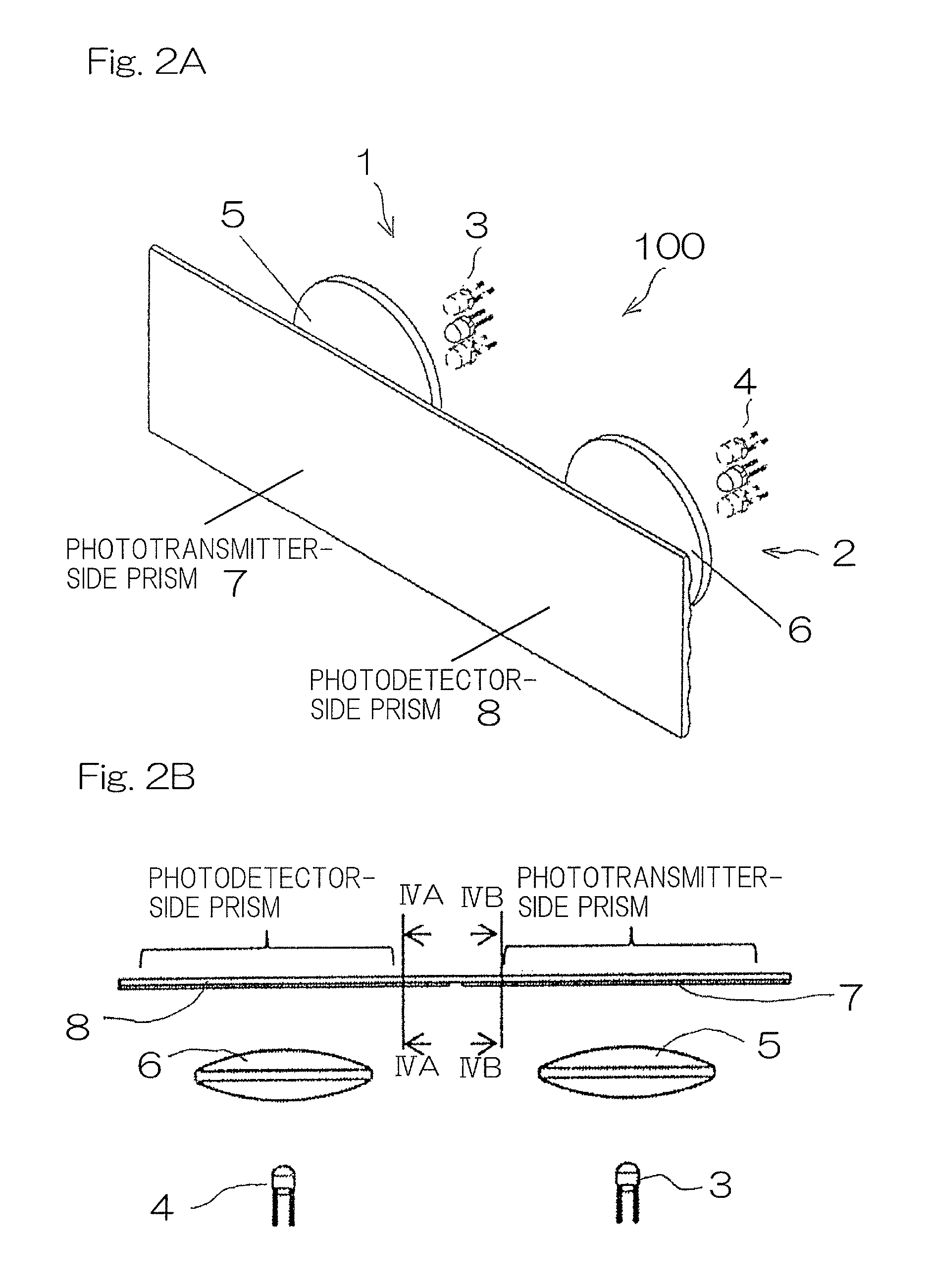
[0019]Preferably, each of the optical divider is a prism having a plurality of prism surface that varies an angle of traveling direction of the detection ray, to a plurality of angles. Therefore, the division areas can be easily formed.

Problems solved by technology

When this sensor is used as an automatic door sensor, the longer a distance between the sensor and a division area of the detection area is, that is, the farther the division area of the detection area is from the automatic door toward the external region, the lower the detection sensitivity is likely to become.
Therefore, in a case where a door is to be immediately opened for a person approaching the automatic door from the external region, a detection sensitivity for the distant division area is low and detection becomes difficult, to reduce a response speed.
However, enhancement of detection sensitivity leads to increase of an influence of a noise, and an S / N ratio cannot be improved, to make improvement of detection performance difficult.
On the one hand, in a division area close to the automatic door, detection sensitivity is unnecessarily enhanced due to a short distance from the sensor, so that malfunction is likely to occur.
Thus, in the case as described above, in the distant division area, detection performance cannot be improved, whereas, in the close division area, detection sensitivity is unnecessarily enhanced to increase the number of times of malfunction, and the sensor is impractical.
However, a mechanism for moving or rotating a prism the angle of which is gradually varied is necessary, and detection performance cannot be sufficiently improved for the distant division area.

Method used


Image

  • Active object detection sensor
  • Active object detection sensor
  • Active object detection sensor

Examples


Embodiment Construction

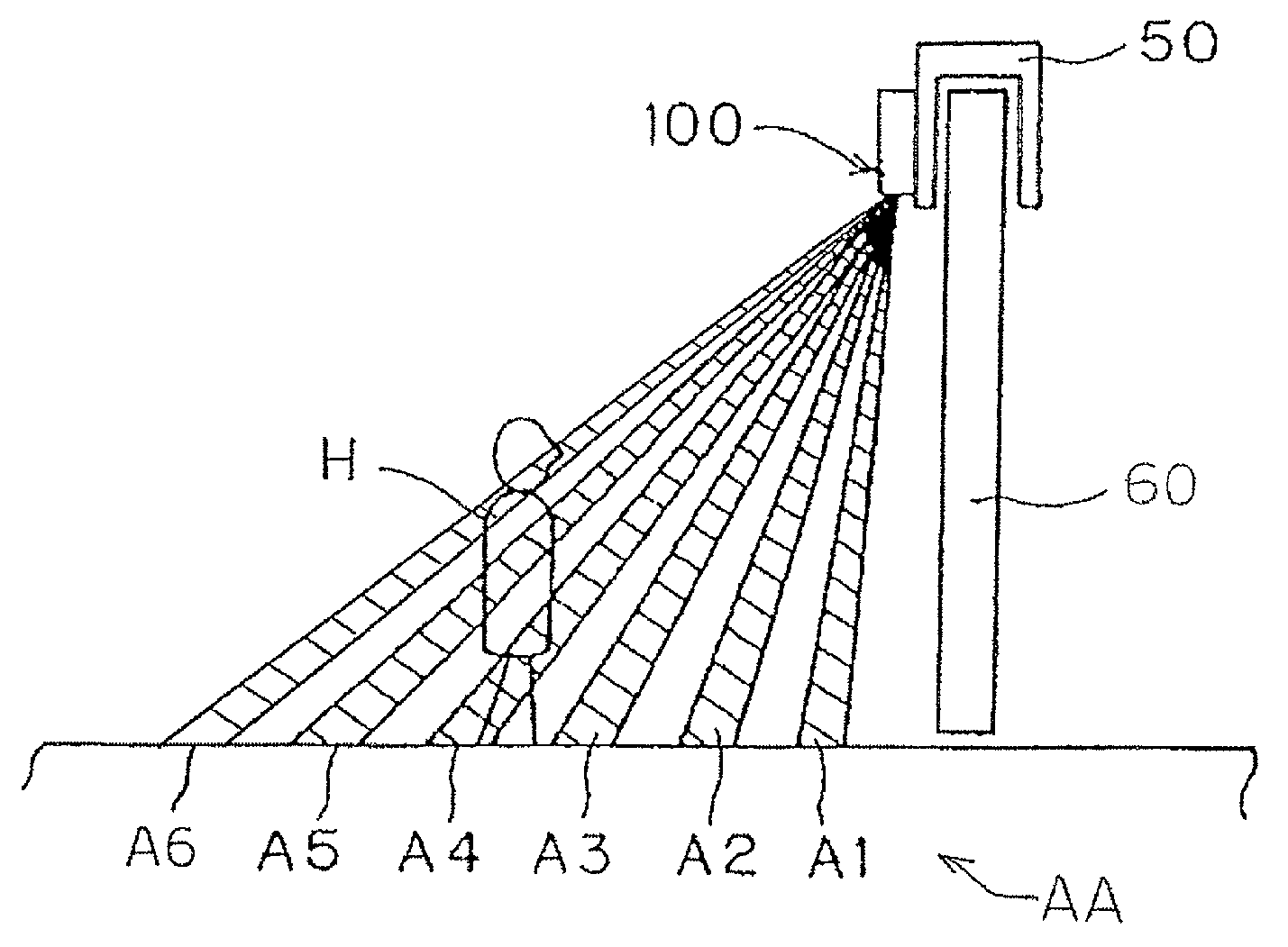
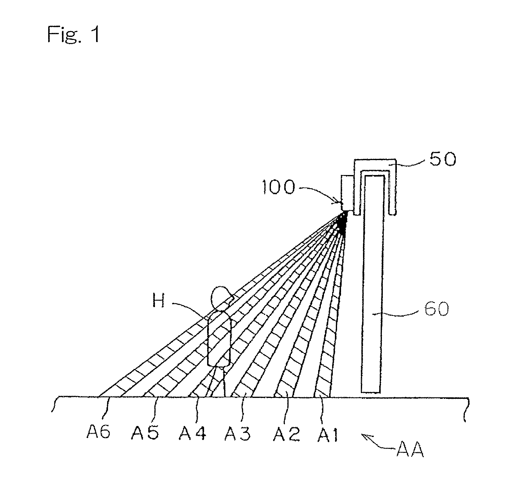
[0034]Hereinafter, one embodiment of the present invention will be described with reference to the drawings. FIG. 1 illustrates a detection area AA, as viewed from a sliding direction of an automatic door 60, in the case of an active object detection sensor 100 for use in an automatic door being used for starting an opening / closing controller of the automatic door, according to one embodiment of the present invention. As shown in FIG. 1, the active object detection sensor 100 is provided in a transom 50, and the detection area AA is formed by six lines of division areas A1 to A6 in the longitudinal direction, from a position close to the sensor 100 toward a position distant from the sensor 100. In the detection area AA, an object such as a human body H is detected. It is to be noted that a plurality of division areas are formed also in the lateral direction for each of the division areas A1 to A6 of the six lines, which lateral division areas are not shown. The plurality of areas in...


PUM


Abstract

Transmitter elements to transmit a detection ray for object detection, to a transmission area, receiver elements to receive, from a reception area, the detection ray reflected by an object, and a transmission-side optical divider and a reception-side optical divider, disposed in front of the transmitter elements and the receiver elements, respectively, which includes optical dividing pieces having optical deflection surfaces on which a traveling direction angle of the detection ray is varied to angles so as to correspond to division areas, are provided. In the optical dividers, a ratio of an area of a second optical deflection surface that forms a division area that is closer to the sensor, relative to an area of a first optical deflection surface that forms a division area that is farther from the sensor, is set so as to be different between a transmission side and a reception side.

Description

CROSS REFERENCE TO THE RELATED APPLICATION[0001]This application is based on and claims Convention priority to Japanese patent application No. 2013-254721, filed Dec. 10, 2013, the entire disclosure of which is herein incorporated by reference as a part of this application.BACKGROUND OF THE INVENTION[0002]1. Field of the Invention[0003]The present invention relates to an active object detection sensor that transmits detection rays for object detection toward a detection area, and detects an object based on a reception signal generated when receiving detection rays reflected by the object.[0004]2. Description of Related Art[0005]To date, an active object detection sensor has been known which transmits detection rays, such as infrared rays or near infrared rays, for object detection, from a transmitter toward a detection area, causes a receiver to receive detection rays reflected by an object and to generate a reception signal, and detects an object such as a human body when the recep...

Claims


Application Information

Patent Timeline
Patent Type & Authority Patents(United States)
IPC IPC(8): G01S17/02G01J5/00G01S17/46G01S7/481G01S17/04
CPCG01S17/026G01J5/0025G01S17/46G01S7/4816G01S7/4815G01S17/04
Inventor SHIMOJI, KENTAIKEDA, TAKAYASUSHIMAZU, MASAYUKIMAEDA, TAKUYA
Owner OPTEX CO LTD
Learn More