Vertebral column traction device and method

Active Publication Date: 2017-08-01
PLEASANTS DONALD A
View PDF24 Cites 4 Cited by
  • Summary
  • Abstract
  • Description
  • Claims
  • Application Information

AI Technical Summary

Benefits of technology

The patent is about a device that prevents a person's body from moving horizontally on a support surface. This is important for ensuring safe and secure training or workouts. The device is made of a braking body that is positioned below the person's body and prevents it from moving on the surface.

Problems solved by technology

Mechanical back problems are due to the way a person's spine moves in relation to certain body movements.
The resultant loss of cushioning ability can lead to back pain if the back is stressed.
Spinal injuries such as sprains or fractures can cause either short term or chronic back pain.
Stretching these muscles beyond their normal extension results in small tears in the muscle tissue.
The muscles are resultantly weakened and may not maintain proper spinal alignment.
The less stable spinal column results in lower back pain.
None, however completely satisfies the requirements for a complete solution to the aforestated problem.
Although the aforementioned prior art have contributed to the development of the art of securing an object to a support member, none of these prior art patents have solved the needs of this art.

Method used


Image

  • Vertebral column traction device and method
  • Vertebral column traction device and method
  • Vertebral column traction device and method

Examples


Embodiment Construction

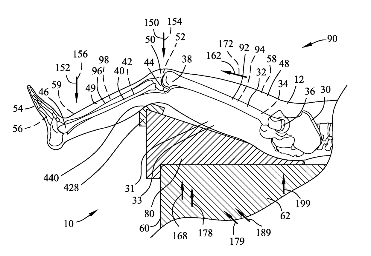
[0100]Description of Anatomy

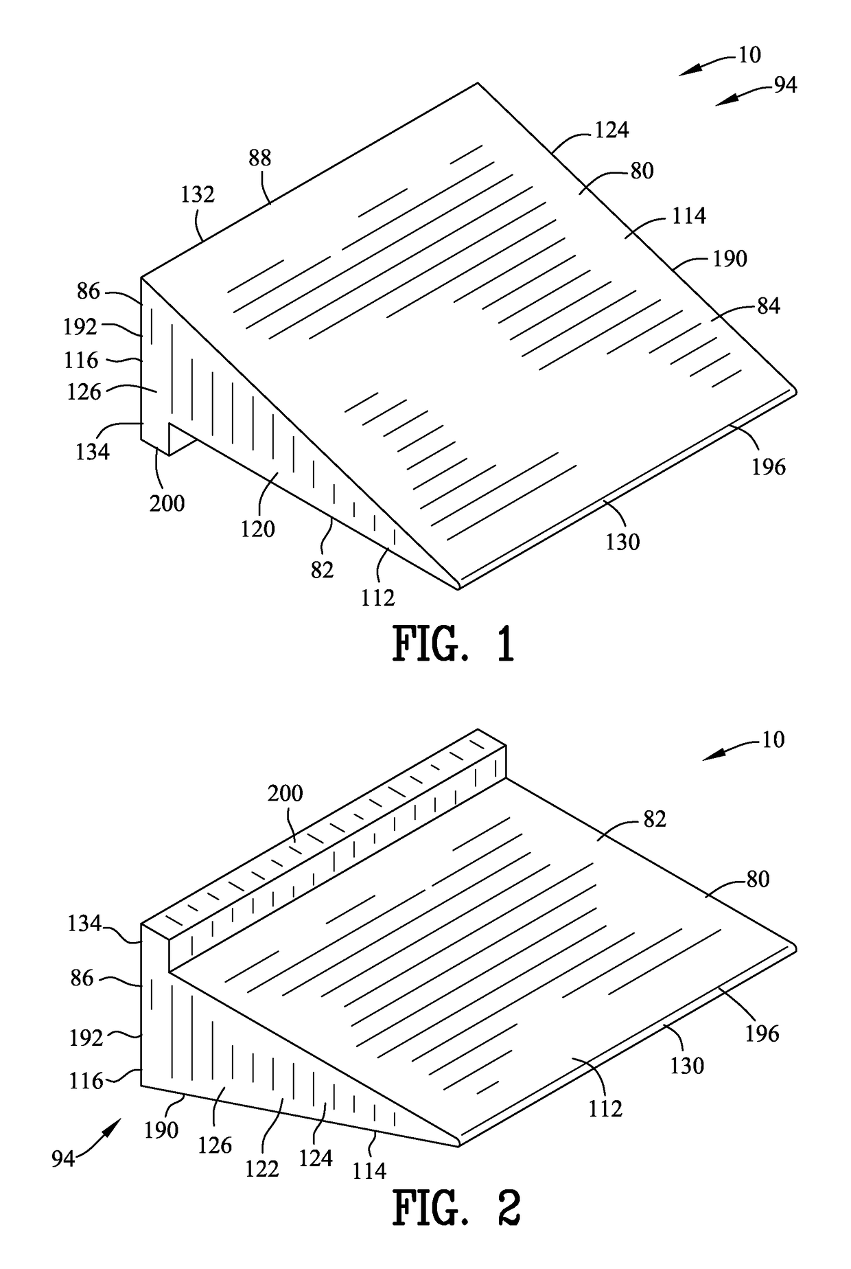
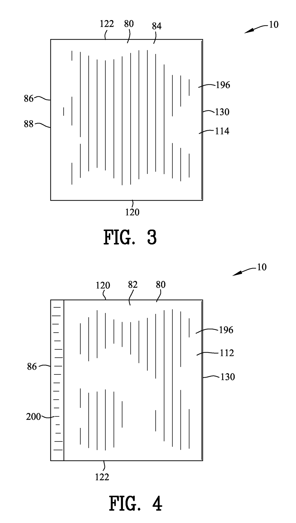
[0101]FIGS. 1-8, 11, 13-15 and 17 are various views of a vertebral column traction device 10 for expanding the vertebral column 20 of an individual 12. The vertebral column traction device 10 also releases pressure between the vertebral column 20 of an individual 12. As best shown in FIGS. 9-12 and 15-18, the vertebral column 20 extends between an upper column end 22 and a lower column end 24. The vertebral column 20 includes a plurality of vertebrae 26 separated and kept apart by a plurality of intervertebral discs 28. Each of the plurality of vertebrae 26 include a foramen transversium 13. The foramen 13 are the areas or spaces or “openings” between the vertebrae 26 where nerves 14 exit the spinal canal 16 and run down to the legs 31 and 33, in the case of the lumbar spine 17.

[0102]A pelvis 30 is coupled to the lower column end 24 of the vertebral column 20. A first leg 31 and a second leg 32 include a first femur 32 and a second femur 34 extend between...


PUM


Abstract

A vertebral column traction device is disclosed for expanding the vertebral column of an individual. The vertebral column traction device comprises a support body having a front surface generally adjacent to a first femur and a second femur for creating a first inclined orientation and a second inclined orientation respectively. A rear surface of the support body is distanced from a first tibia and a second tibia for creating a first cantilever orientation and a second cantilever orientation respectively. A pivot area of the support body is generally adjacent to the first tibia and the second tibia for defining a first fulcrum and a second fulcrum respectively. A first lever and the second lever are defined about the first fulcrum and the second fulcrum respectively for expanding the vertebral column.

Description

CROSS-REFERENCE TO RELATED APPLICATIONS[0001]This application claims benefit of U.S. Patent Provisional application No. 61 / 641,277 filed May 1, 2012. All subject matter set forth in provisional application No. 61 / 641,277 is hereby incorporated by reference into the present application as if fully set forth herein.BACKGROUND OF THE INVENTION[0002]Field of the Invention[0003]This invention relates to traction and more particularly to a vertebral column traction device for expanding the vertebral column of an individual.[0004]Background of the Invention[0005]It has been estimated that between sixty and eighty percent of the population will experience back pain at some point during their lives. Common causes for back pain include nerve and muscular problems, as well as degenerative disc disease. Mechanical back problems are due to the way a person's spine moves in relation to certain body movements.[0006]One of the most common mechanical causes of back pain is intervertebral disc degene...

Claims


Application Information

Patent Timeline
IPC IPC(8): A61B6/04A61H1/02A61H1/00
CPCA61H1/0292A61H1/00A61H1/0218A61H2201/0134A61H2201/1284A61H2201/1609A61H2201/164A61H2201/168A61H2203/0456
Inventor PLEASANTS, DONALD A.
Owner PLEASANTS DONALD A
Why Eureka
Try Eureka