
Implant delivery system

a technology of implanted and stent, which is applied in the field of implanted delivery systems, can solve the problems of user position, low stability, and low flexibility of micro-coils, and achieve the effect of minimizing the surface temperature of the device and short detachment tim

Active Publication Date: 2017-08-01
MICROVENTION INC
View PDF53 Cites 194 Cited by
  • Summary
  • Abstract
  • Description
  • Claims
  • Application Information

AI Technical Summary

Benefits of technology

This solution provides reliable and efficient implant detachment with minimal surface temperature increase and short detachment time, while ensuring the implant does not reattach, and offers clear user feedback on successful detachment through electrical resistance measurement.

Problems solved by technology

Microcoils are extremely flexible and have very little structural integrity.
While implant delivery and detachment systems are known in the art, they do not provide the user feedback that the implant has indeed detached from the delivery device.
These delivery devices leave the user in the position of wondering whether heat etc., has been applied long enough to cause detachment.

Method used


Image

  • Implant delivery system
  • Implant delivery system
  • Implant delivery system

Examples


Embodiment Construction

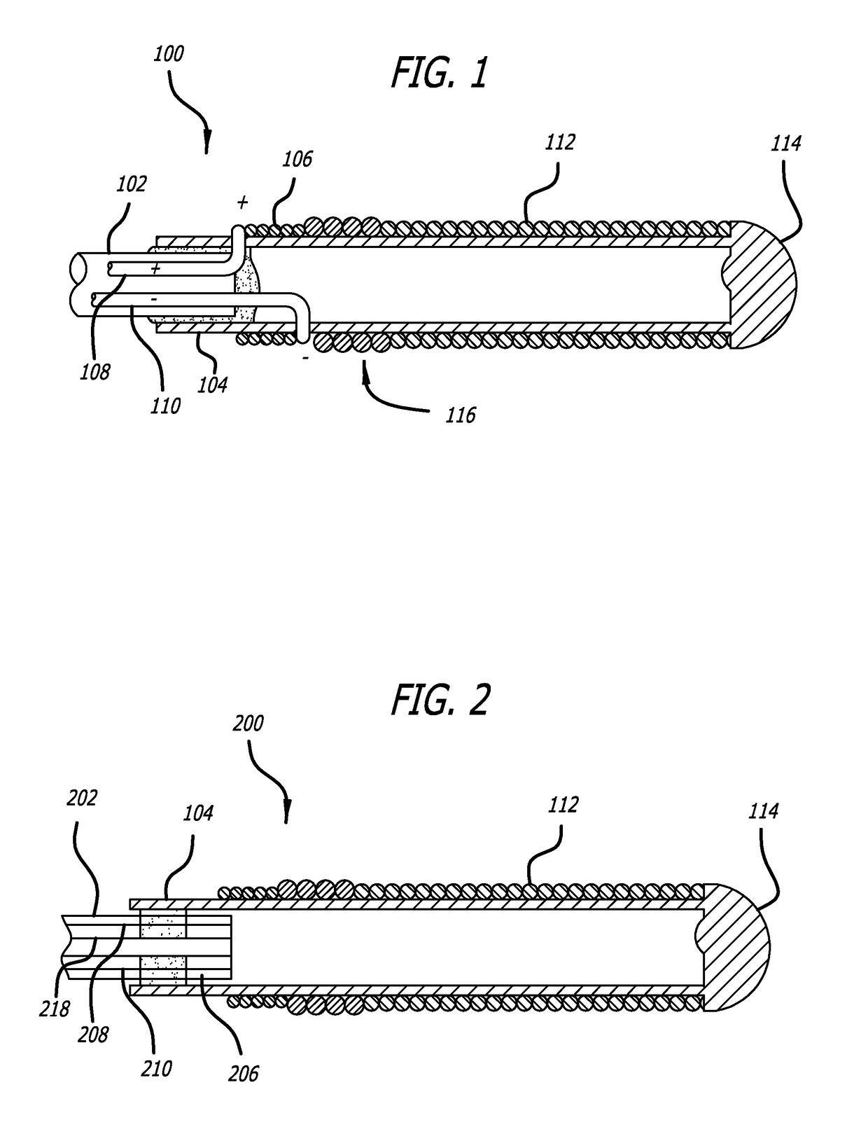
[0044]Turning to FIG. 1, a detachment system 100 of the present invention, and specifically the distal portion of the detachment system 100, is illustrated. The detachment system 100 includes a pusher 102 that is preferably flexible. The pusher 102 is configured for use in advancing an implant device 112 into and within the body of a patient and, specifically, into a target cavity site for implantation and delivery of the implant device 112. Potential target cavity sites include but are not limited to blood vessels and vascular sites (e.g., aneurysms and fistula), heart openings and defects (e.g., the left atrial appendage), and other luminal organs (e.g., fallopian tubes).

[0045]A stretch-resistant tether 104 detachably couples the implant 112 to the pusher 102. In this example, the tether 104 is a plastic tube that is bonded to the pusher 102. A substantially solid cylinder could also be a design choice for the tether 104. The stretch resistant tether 104 extends at least partially...


PUM


Abstract

A system and method of delivering and detaching an implant within a body of a patient is described. A tether connects an implant with a delivery device. The delivery device includes a heater coil through which the tether passes. The inner diameter of the heater coil is about the same size or slightly larger than the outer diameter of the tether, allowing the tether to more efficiently break the tether during delivery.

Description

RELATED APPLICATIONS[0001]This application claims the benefit of U.S. Provisional Application No. 61 / 169,629, filed Apr. 15, 2009 entitled Implant Delivery System, whose contents are hereby incorporated by reference.FIELD OF THE INVENTION[0002]The present invention relates to systems and methods for delivering implant devices to a target site or location within the body of a patient. The present invention also relates to a method of detecting implant detachment within the body of a patient.BACKGROUND OF THE INVENTION[0003]Delivery of implantable therapeutic devices by less invasive means has been demonstrated to be desirable in numerous clinical situations. For example, vascular embolization has been used to control vascular bleeding, to occlude the blood supply to tumors, to occlude fallopian tubes, and to occlude vascular aneurysms, particularly intracranial aneurysms. In recent years, vascular embolization for the treatment of aneurysms has received much attention. Implants used ...

Claims


Application Information

Patent Timeline
Patent Type & Authority Patents(United States)
IPC IPC(8): A61F11/00A61B17/12A61F2/95A61F2/01A61B90/00
CPCA61B17/12022A61B17/12113A61B17/12154A61F2/95A61B90/39A61B2017/12068A61F2002/011A61F2002/9505A61F2002/9511A61F2250/0071A61F2/011A61F2/01
Inventor TIEU, TAI D.MORITA, HIDEONGUYEN, HELEN
Owner MICROVENTION INC
Learn More