
Pressure sensitive device for flow detection

a technology of flow detection and pressure sensitive devices, which is applied in the direction of fluid pressure measurement using elastically deformable gauges, other medical devices, inhalators, etc., can solve the problems of signal processing or other procedures, high manufacturing cost of these pressure sensors,

Active Publication Date: 2017-07-25
ARROW ELECTRONICS
View PDF6 Cites 54 Cited by
  • Summary
  • Abstract
  • Description
  • Claims
  • Application Information

AI Technical Summary

Benefits of technology

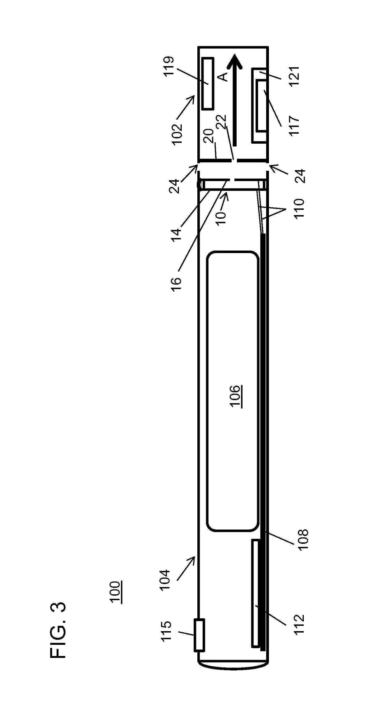
The patent text describes a pressure sensitive device that can detect and measure pressure. The device includes a ring with two membranes, one of which is flexible and connected to the ring with a conductive portion. The other membrane is perforated and spaced apart from the first membrane. The device can detect a pressure difference between the membranes, which causes a change in the electrical properties of the device. This allows the device to be used as an electronic inhalation device, where the pressure difference triggers the release of material from a chamber in the device. The patent also includes a method for fabricating the pressure sensitive device and a diagram showing the structure of the device. The technical back of the invention is to provide a reliable and sensitive way to measure pressure and use it in electronic inhalation devices.

Problems solved by technology

Many of these pressure sensors are expensive to manufacture and require signal processing or other procedures to obtain measurements.

Method used


Image

  • Pressure sensitive device for flow detection
  • Pressure sensitive device for flow detection
  • Pressure sensitive device for flow detection

Examples


Embodiment Construction

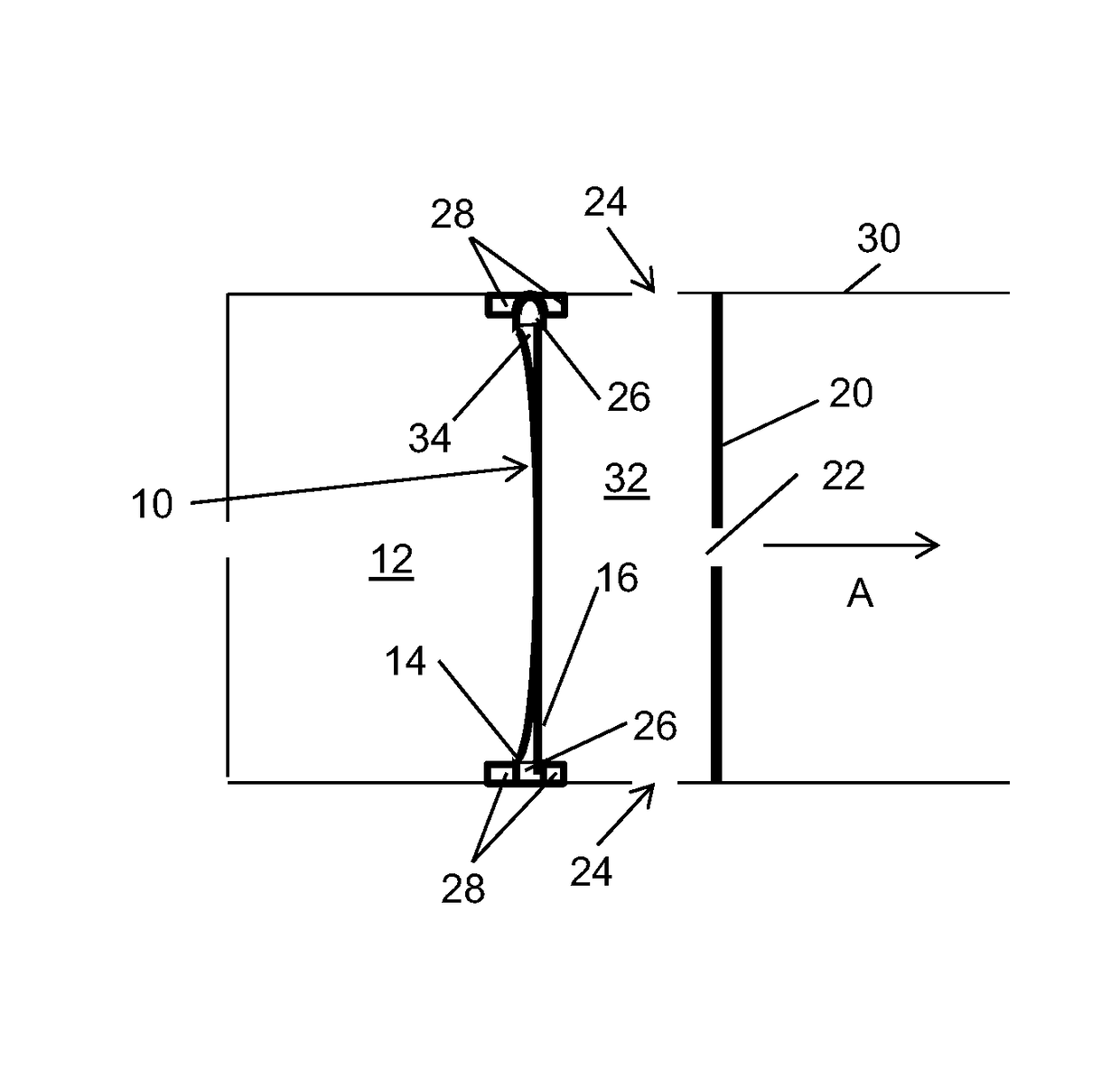
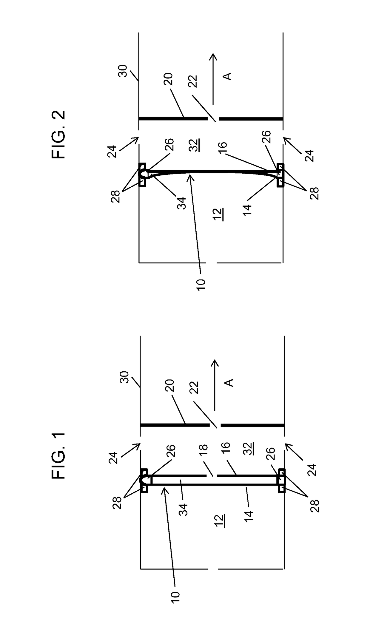
[0022]In accordance with the present principles, a pressure sensitive device is employed to detect the presence of a pressure differential created due to fluid flow. The pressure sensitive device includes components configured to react to a particular pressure differential to provide a pressure switch. When fluid flow causes a sufficient pressure differential between the two sides of the pressure sensitive device, at least one of the sides deflects or distorts to cause an electrical change such as electrical contact or a capacitive change between two surfaces allowing a signal to be transmitted between the two sides.

[0023]In one embodiment, the pressure sensitive device sensor utilizes two conductive pads on a flexible substrate that are separated by a very small gap dependent on a pressure to be sensed. There are lead wires coupled to each conductive side to permit a signal to pass through when the two conductive sides are in contact with one another. A hole is present in on one co...


PUM

PropertyMeasurementUnit
flexibleaaaaaaaaaa
threshold pressureaaaaaaaaaa
electrical propertyaaaaaaaaaa

Abstract

A pressure sensitive device includes a ring having a central axis, first side and second side. The ring includes a dielectric portion parallel to the central axis and between the first and second sides. A flexible membrane is connected to a periphery of the ring on the first side, the flexible membrane including a conductive portion. A perforated membrane is connected to a periphery of the ring on the second side. The perforated membrane is spaced apart and electrically isolated from the flexible membrane by the ring below a threshold pressure differential across the pressure sensitive device. The perforated membrane includes an opening therethrough and a conductive portion facing and corresponding to the conductive portion of the flexible membrane such that a threshold pressure differential across the pressure sensitive device causes deflection between the conductive portions of the flexible membrane and the perforated membrane to change an electrical property.

Description

BACKGROUND[0001]Technical Field[0002]The present invention relates to pressure sensors, and more particularly to a pressure sensitive device that deforms to change an electrical property in the presence of a pressure differential.[0003]Description of the Related Art[0004]Pressure sensors measure fluid pressure. A pressure sensor usually acts as a transducer that transmits an electrical signal as a function of the pressure imposed. Pressure sensors are employed for control and monitoring in many applications. Pressure sensors can also be used to indirectly measure other variables such as fluid / gas flow, speed, water level, and altitude. Pressure sensors may employ different technologies, for example, piezoresistive strain gauge, capacitive, electromagnetic, piezoelectric, optical, potentiometric, etc. Many of these pressure sensors are expensive to manufacture and require signal processing or other procedures to obtain measurements.SUMMARY[0005]A pressure sensitive device includes a ...

Claims


Application Information

Patent Timeline
Patent Type & Authority Patents(United States)
IPC IPC(8): A61M15/00A24F47/00A61M11/04A61M15/06G01L7/08A61M16/00H01H35/34A24F40/10A24F40/485A24F40/51A24F40/70
CPCG01L7/08A24F47/008A61M11/042A61M15/06A61M2016/0024A61M2205/8206A61M2207/00H01H35/346Y10T29/49155A24F40/10A24F40/51A24F40/70A24F40/485
Inventor POWERS, NICHOLASCURTIS, CHRISTIAN
Owner ARROW ELECTRONICS
Learn More