
Display device with photovoltaic cells integrated into the screen and improved screen luminosity and reflectivity

a technology of photovoltaic cells and display devices, which is applied in the direction of static indicating devices, instruments, optical elements, etc., can solve the problems of increasing cost, small manufacturing tolerances of such a lenticular array, and the residual thickness between the lens and the semi-transparent photovoltaic module,

Active Publication Date: 2017-07-18
GARMIN
View PDF12 Cites 2 Cited by
  • Summary
  • Abstract
  • Description
  • Claims
  • Application Information

AI Technical Summary

Benefits of technology

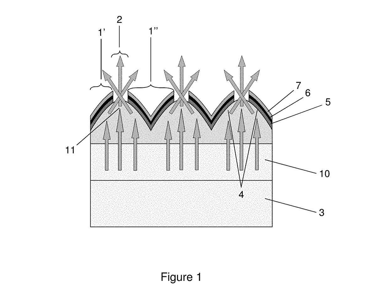
[0018]According to one variant embodiment, the material from which the surface of the concentrators is made is an electrical conductor that also serves as an electrode for the photovoltaic active zones. Thus, this combination of the reflective surface of the concentrator and one of the two electrodes of the photovoltaic module allows the number of layers of the device to be decreased, and thus its thickness to be minimized.
[0020]According to another embodiment, said photovoltaic active zones cover and are conformal to the surface of the concentrators of light. The advantage of this configuration is that it maximizes the visible area of the photovoltaic active zones, and therefore potentially maximizes the electrical production generated by the photovoltaic module.
[0023]According to an additional variant embodiment (not shown) the concentrators are textured level with areas that are in the vicinity of the tops of said concentrators and that correspond to the orifices. Texturing the surfaces at the top of said concentrators makes it possible to minimise reflection of light at the interfaces between two optical media of different refractive indices, and thus to maximize the amount of light emitted through said concentrators.
[0024]In one particular embodiment (not shown) the display device according to the invention furthermore comprises a collimating device able to direct the light emitted by the light sources in a preferred direction. Specifically, all the concentrators have a constrained cone of acceptance of incident light, i.e. an angle of incidence limit beyond which the incident light is no longer focused but expelled from the optical system. This acceptance cone depends on the shape of the concentrators and as the degree of concentration increases, i.e. as the ratio of the entrance area of the light flux to the exit area of the light flux increases, this acceptance cone becomes more and more limited. A device for collimating the incident light allows the direction, and therefore the angle of incidence of the light emitted by the device, to be controlled so that it advantageously corresponds to the acceptance cone of the concentrators even when this current is narrow. Combining a collimating device with the device of the invention therefore makes it possible to maximize the degree of concentration. Thus, for a given fractional photovoltaic active zone area, the amount of light that is transmitted by the concentrators through the orifices of the photovoltaic module is increased.

Problems solved by technology

Portable devices are generally supplied with power by batteries and the lifetime of these batteries is a major factor affecting the user-friendliness of the device.
Nevertheless, the lenticular arrays used in the known documents of the prior art are not the most effective optical systems for productively concentrating the light emitted by the device, i.e. for focusing an incident light beam onto a point-like region of space.
Moreover, the manufacturing tolerances of such a lenticular array, especially regarding the residual thickness between the lenses and the semitransparent photovoltaic module, and the alignment of respective transparent zones of the photovoltaic module relative to the micro-lenses, are very small.
In addition, the material from which the lenticular array is made has a calibrated refractive index that increases cost and creates process constraints.
Lastly, the optical adhesives of different refractive indices to that of the lenticular array, which are used as adhesives to assemble the lenticular array in the screen, cause, at the various refractive index differences, losses in transmission of the light emitted by the device, and parasitic reflections of ambient light from the screen.

Method used


Image

  • Display device with photovoltaic cells integrated into the screen and improved screen luminosity and reflectivity
  • Display device with photovoltaic cells integrated into the screen and improved screen luminosity and reflectivity
  • Display device with photovoltaic cells integrated into the screen and improved screen luminosity and reflectivity

Examples


Embodiment Construction

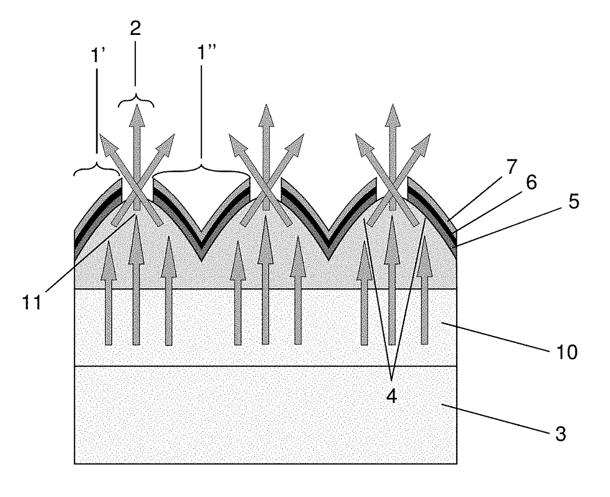
[0074]With reference to FIG. 1, which corresponds to a schematic cross-sectional view of the display device according to the invention comprising: a plurality of photovoltaic active zones 1 and a plurality of orifices 2, two neighboring photovoltaic active zones 1′, 1″ forming one orifice 2; a source 3 of artificial light; and a plurality of opaque and reflective parabolic-shaped concentrators 4 placed between said light sources 3 and said photovoltaic active zones 1. Said parabolic concentrators 4 are arranged so that the light emitted by the sources 3 of artificial light is directed by the concentrators 4 of light through the orifices 2.

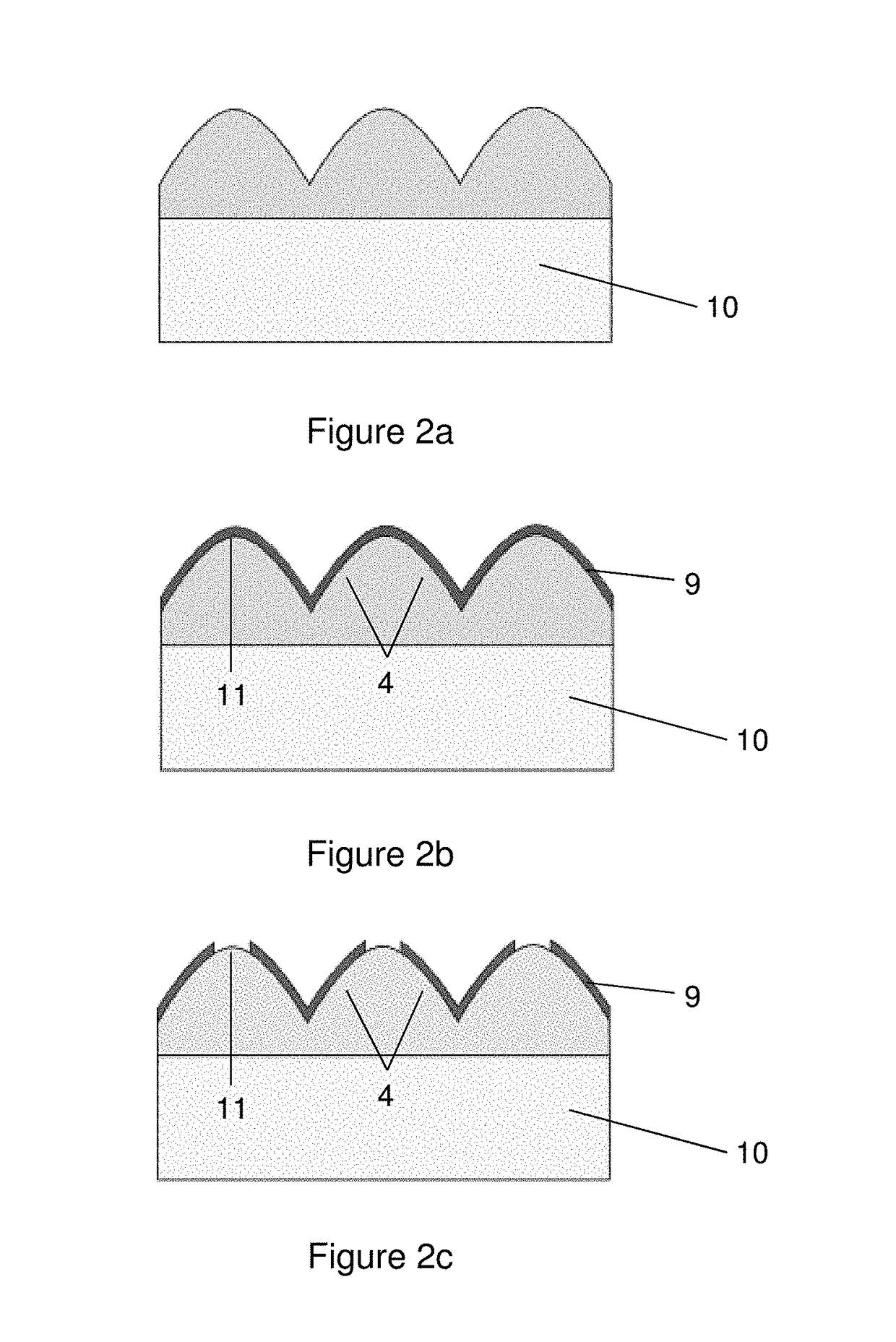
[0075]FIGS. 2a, 2b, 2c and 2d schematically show a plurality of objects that illustrate various steps of a first process for manufacturing one portion of the display device according to the invention in cross section. The first steps consist in providing a transparent sheet 10 and in structuring said transparent sheet 10 by moulding a layer of mate...


PUM

PropertyMeasurementUnit
electricalaaaaaaaaaa
shapeaaaaaaaaaa
transparentaaaaaaaaaa

Abstract

A display device comprising at least: (a) a plurality of photovoltaic active areas and a plurality of holes, two neighboring photovoltaic active areas forming an opening; (b) one or more artificial light sources; (c) a plurality of light concentrators and reflective opaque disposed between said light sources and said photovoltaic active areas. This device wherein said hubs of light are arranged so that the light emitted from artificial light sources is directed by the light concentrators through the holes.

Description

TECHNICAL FIELD OF THE INVENTION[0001]The present invention relates to emissive display screens, and more particularly to the backlit display screens of nonportable or portable electronic devices, having photovoltaic cells integrated into the screen.PRIOR ART[0002]In the present invention, the expression “display device” refers to an electronic device equipped with a screen that allows a luminous message or image to be displayed by a suitable guidance of the light generated by said device. Display screens comprising backlit image zones are widely used in portable electronic devices. The expression “backlit image zone” is understood to mean an image zone that is located in front of a light source that illuminates it from behind. The “image zone” may for example be a pixel, a plurality of pixels or one portion of a pixel (a liquid-crystal pixel for example), or even a strip of film on which an image has been printed. In a backlit screen, a diffuse light source is placed upstream of th...

Claims


Application Information

Patent Timeline
Patent Type & Authority Patents(United States)
IPC IPC(8): H01J40/00H01L31/054H01L33/00H01L31/153H01L31/0224G02B19/00H01L31/042G02F1/133
CPCH01L31/0547G02B19/0028G02B19/0038G02B19/0085H01L31/022425H01L31/042H01L31/153H01L33/00G02F2001/13324Y02E10/52G02F1/13324
Inventor KERZABI, BADRECHAPPAZ, CYRILCENNE, ALAINDE VECCHI, SYLVAIN
Owner GARMIN
Learn More