Via structures for solar cell interconnection in solar module

a solar module and structure technology, applied in the field of contact metallization of photovoltaic cells, can solve the problems of voids, voids, and inability to contact, and achieve the effect of reducing the number of voids

Active Publication Date: 2017-07-18
ALTA DEVICES INC
View PDF8 Cites 0 Cited by
  • Summary
  • Abstract
  • Description
  • Claims
  • Application Information

AI Technical Summary

Benefits of technology

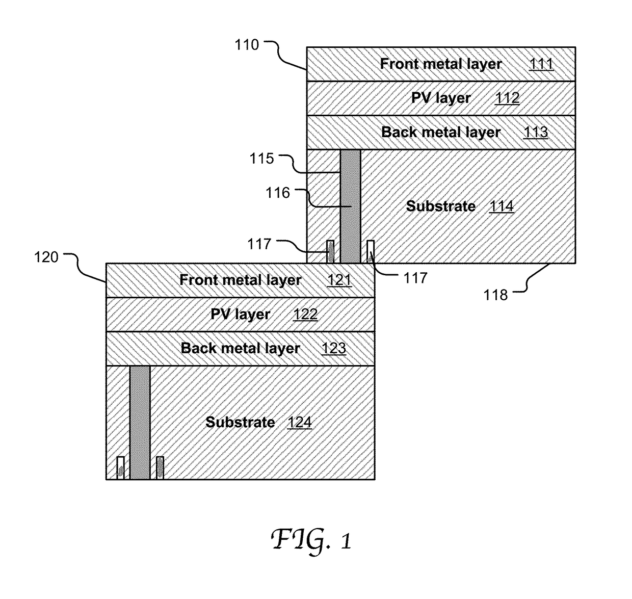
[0007]Therefore, it would be advantageous to provide a cell interconnection mechanism offering void-free electrical contacts through back via fillings and yet without causing short circuit.
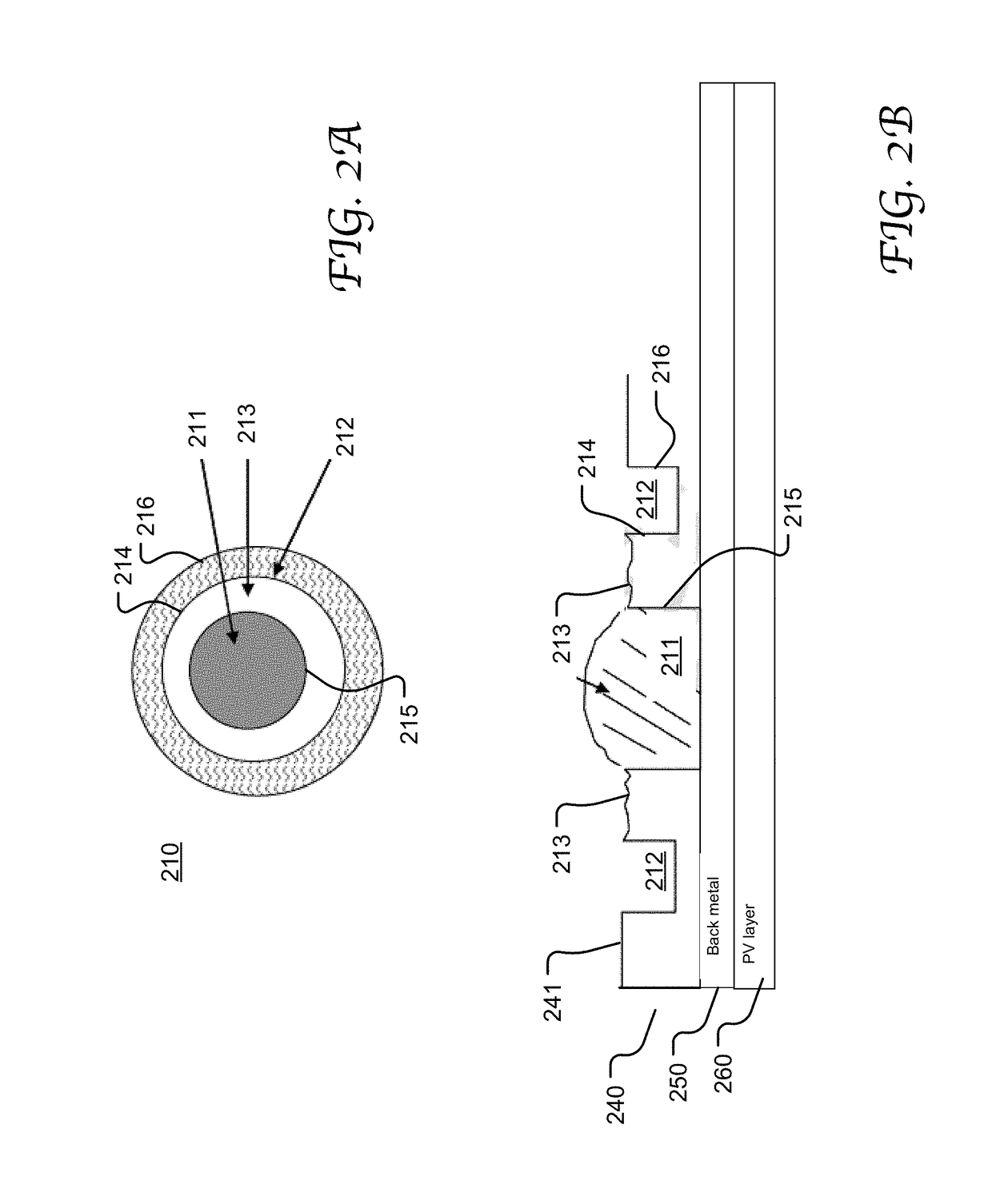
[0009]The overflow capture region around a via allows an overfill of the conductive material, which beneficially ensures a void-free via, and advantageously controls the overflow of the filling to a deterministic region. As the excessive filling would not spread to unintended areas, the potential short circuit issue related to the overflow is advantageously eliminated. Thus, it is no longer needed to form additional insulation between the front and the back electrodes in a solar cell to prevent short circuit as would be performed in the conventional approach. As a result, the solar cell productivity and reliability can be increased, and the manufacturing time and cost are saved.

Problems solved by technology

In practice, a back via is usually subject to overfill with the conductive material to prevent the formation of a void inside the via which can potentially lead to a failed contact.
However, filling a back via with excess conductive material tends to cause an uncontrolled lateral overflow (or smear) of the conductive material from the via, especially when the two solar cells are stacked and pressed together for integration.
Unfortunately, many contributing factors make it difficult to determine a precise amount of the conductive material for a void-free via without resulting in overflow, such as the variations in the volume control capability of material placement, via size variations, and material property changes over time, temperature, moisture, contact surface, and etc.
The conductive material overflow in a solar cell can undesirably reach and bridge the front and back electrodes of another solar cell (e.g., the lower solar cell) and cause short circuit.
Unfortunately, this contributes to significantly increased manufacturing cost and time.

Method used


Image

  • Via structures for solar cell interconnection in solar module
  • Via structures for solar cell interconnection in solar module
  • Via structures for solar cell interconnection in solar module

Examples


Embodiment Construction

[0024]Reference will now be made in detail to the preferred embodiments of the present invention, examples of which are illustrated in the accompanying drawings. While the invention will be described in conjunction with the preferred embodiments, it will be understood that they are not intended to limit the invention to these embodiments. On the contrary, the invention is intended to cover alternatives, modifications and equivalents, which may be included within the spirit and scope of the invention as defined by the appended claims. Furthermore, in the following detailed description of embodiments of the present invention, numerous specific details are set forth in order to provide a thorough understanding of the present invention. However, it will be recognized by one of ordinary skill in the art that the present invention may be practiced without these specific details. In other instances, well-known methods, procedures, components, and circuits have not been described in detail ...


PUM


Abstract

System and method of providing a photovoltaic (PV) cell with a complex via structure in the substrate that has a primary via for containing a conductive material and an overflow capture region for capturing an overflow of the conductive material from the primary via. The conductive filling in the primary via may serve as an electrical contact between the PV cell and another PV cell. The overflow capture region includes one or more recesses formed on the substrate back surface. When the conductive material overflows from the primary via, the one or more recesses can capture and confine the overflow within the boundary of the complex via structure. A recess may be a rectangular or circular trench proximate to or overlaying the primary via. The recesses may also be depressions formed by roughening the substrate back surface.

Description

TECHNICAL FIELD[0001]The present disclosure relates generally to the field of photovoltaic cells and, more specifically, to the field of contact metallization on photovoltaic cells.BACKGROUND[0002]A solar cell or photovoltaic (PV) cell is an electrical device that converts the energy of light directly into electricity by photovoltaic effect. Energy generated from solar cells offers renewable, environmentally friendly and readily available alternatives to fossil fuels. Typically a solar cell utilizes a PV layer made of semiconductor materials in the form of a p-n junction for energy conversion. Metal electrodes are laid on the front and the back of the semiconductor materials to conduct the produced voltage and current to external circuitry for power storage or transportation.[0003]An array of solar cells can be interconnected and assembled into a solar module or a solar panel to achieve aggregated current and voltage generated by the individual solar cells. One prevalent approach of...

Claims


Application Information

Patent Timeline
Patent Type & Authority Patents(United States)
IPC IPC(8): H01L31/00H01L31/05
CPCH01L31/0508H01L31/05H01L31/0504H01L31/0445Y02E10/50H01L31/02002H01L31/022441H01L31/02366
Inventor YANG, LINLINHE, GANGPATTERSON, DANGODDU, PAULLAN, LIGUANGHIGASHI, GREGG
Owner ALTA DEVICES INC
Why Eureka
Try Eureka