
Central osteoarticular relief and performance structured load distribution system device and modular scalable vest system

a technology of structured load and distribution system, which is applied in the direction of traveling articles, protective equipment, garment special features, etc., can solve the problems of limiting mobility, not meeting several needs, and often increasing the load being supported or carried by the wearer, so as to reduce fatigue and enhance the mobility of the warfighter

Active Publication Date: 2017-07-11
U S GOVERNMENT DEPT OF THE NAVY U S MARINE CORPS
View PDF11 Cites 7 Cited by
  • Summary
  • Abstract
  • Description
  • Claims
  • Application Information

AI Technical Summary

Benefits of technology

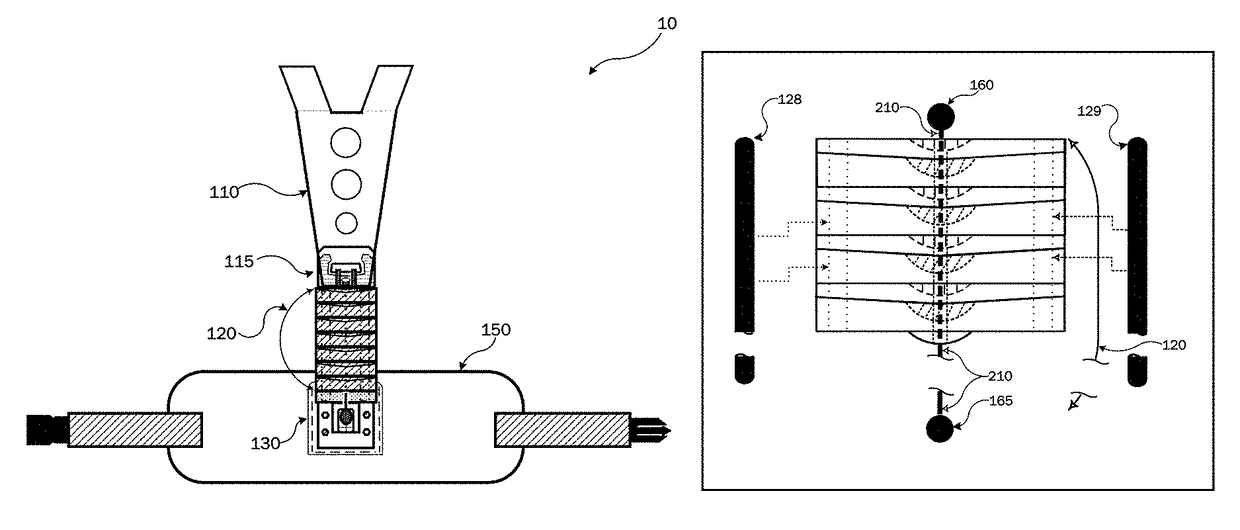
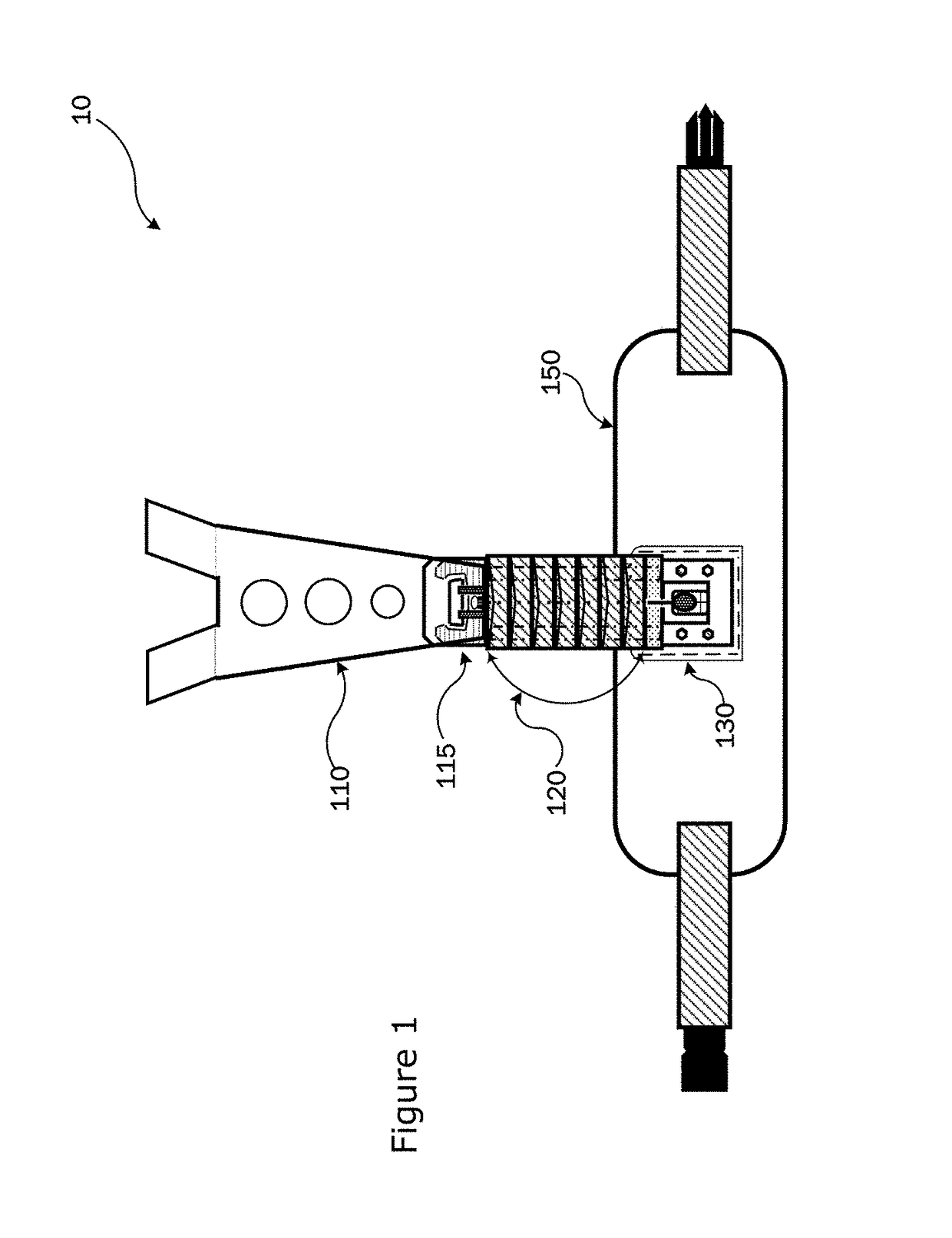
The patent text describes the Modular Scalable Vest (MSV), a new body armor system for the U.S. Marine Corps. The MSV is designed to replace multiple vests with a single, tailorable system that scales from a low-visibility vest up to a level of utility and protective coverage similar to that of the Improved Modular Tactical Vest. It is composed of various components that can be added or removed to create different combat suites with varying levels of protection. The MSV provides improved warfighter mobility and reduced physical exertion, which helps decrease metabolic expenditure. The load distribution device is one of the key features of the MSV system, which helps distribute the weight of the vest and equipment from the user's shoulders to their hips and / or pelvis while maintaining their range of motion.

Problems solved by technology

Moreover, the load that is being supported or carried by the wearer is frequently increased even further due to the addition or carrying of equipment items or gear attached to such vests.
'738, are securely attached to the user through a variety of means such as belts, straps, and etc., the weight of the vest and equipment is, in general, predominantly borne by the user's shoulders and back, which is a factor that can lead to physical distress, may limit mobility, and / or can cause injuries.
While this system might be useful, it is Applicant's belief that the '439 system has the following limitations and / or does not meet several needs: a lack of flexibility in the vertical frame; it does not mimic natural movements of the human spine; there appears to be a limited capability to bend forward at hips and to twist at the torso, and to allow for bending side-to-side; it is worn next to the user; and it is not capable of being rapidly released and / or not capable of being easily dismantled.

Method used


Image

  • Central osteoarticular relief and performance structured load distribution system device and modular scalable vest system
  • Central osteoarticular relief and performance structured load distribution system device and modular scalable vest system
  • Central osteoarticular relief and performance structured load distribution system device and modular scalable vest system

Examples


second embodiment

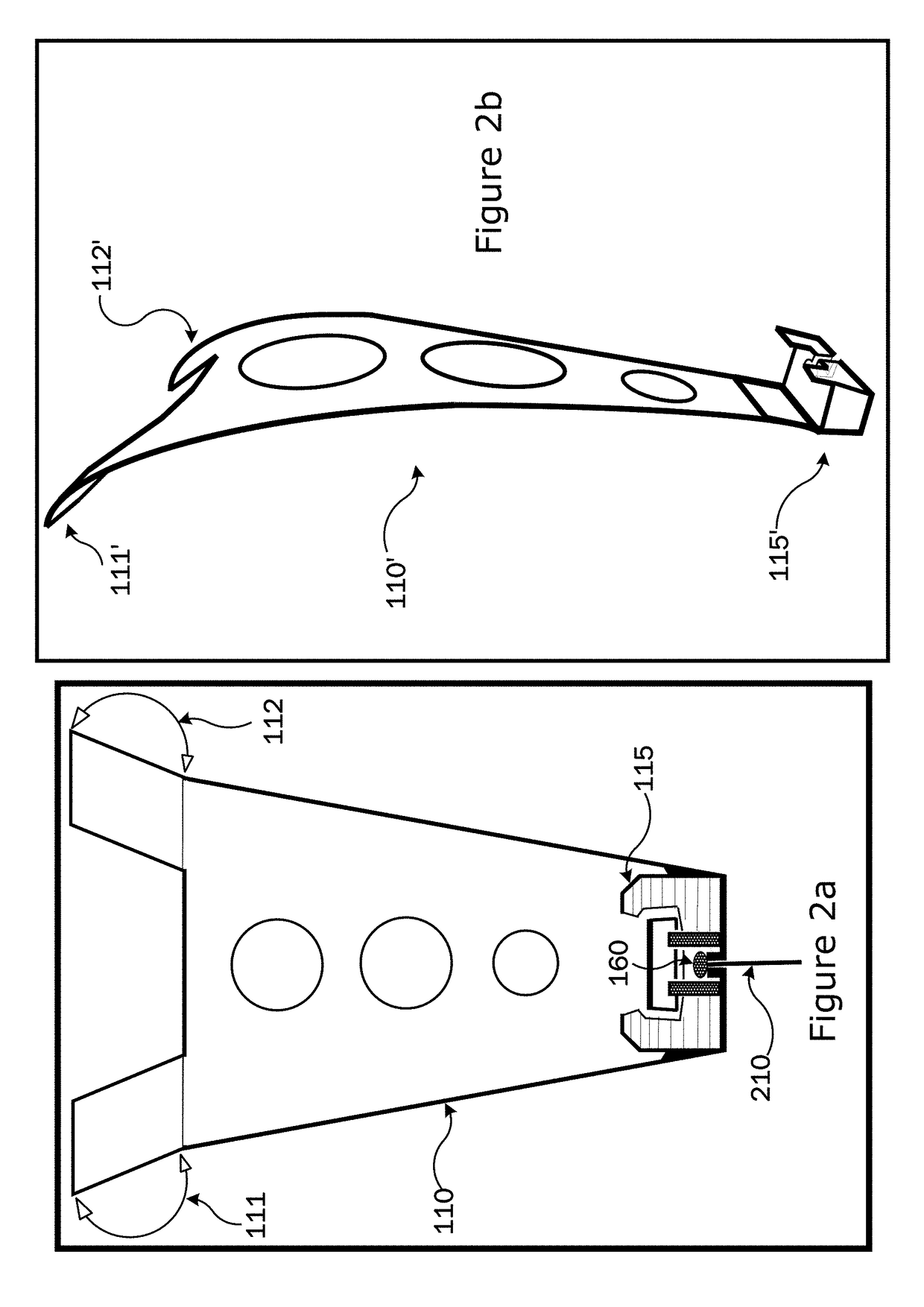
[0058]Referring now to FIGS. 2a (&2b), an embodiment (and a second embodiment shown in 2b) of the 1775 Frame Sheet 110 (&110′) and the Plate Bracket 115 (&115′) are shown. As shown in FIG. 2b, but without limitation, this embodiment of the current design of the 1775 Frame Sheet 110′ is preferably contoured to match the complex curvature of Small Arms Protective Insert (SAPI) / Plate (not shown) utilized by law enforcement and military personnel to provide protection against various types of projectiles.

[0059]Also, without limitation, the 1775 Frame Sheet 110 (&110′) is preferably designed to have vertical extensions (or wing sections) 111&112 as shown in FIG. 2a (or 111′&112′ as shown in FIG. 2b) that extend beyond the vertical dimensions of a SAPI / Plate (not shown), and when a SAPI / Plate is nested in the Plate Bracket 115 as shown in FIG. 2a (or 115′ as shown in FIG. 2b) the SAPI / Plate would ride on the back of the 1775 Frame Sheet 110 (&110′) in an area on or near the user's back, s...


PUM


Abstract

The present invention is a loadbearing device known by the Applicants' as the “Central Osteoarticular Relief and Performance Structured Load Distribution System” (“CORPS-LDS”), which is worn by a user to help distribute the weight of a load being carried or borne by the user. More specifically, the weight is substantially shifted from the user's shoulders to their hips while not overly inhibiting the user's range of motion. Furthermore, it is an aspect of the CORPS-LDS to distribute the weight being carried in a manner that reduces the strain on the spine and back while lessening the metabolic expenditure of the user. Moreover, the present invention is a protective vest system that utilizes the present invention's CORPS-LDS.

Description

STATEMENT REGARDING FEDERALLY SPONSORED RESEARCH OR DEVELOPMENT[0001]The invention described herein may be manufactured and used by or for the Government of the United States of America for any purpose whatsoever without payment of any royalties thereon or therefor.CROSS REFERENCE TO RELATED APPLICATIONS[0002]This non provisional incorporates by reference the entire contents of the prior provisional application No. 61 / 894,059, filed Oct. 22, 2013, and all related submittals are hereby incorporated by reference for all purposes as if fully set forth herein.COPYRIGHT NOTICE[0003]A portion of the disclosure of this document may contain materials that are subject to copyright protection. The copyright owner has no objection to the facsimile reproduction by anyone of this document or disclosure as it appears in the Patent and Trademark Office patent file or records, but otherwise reserves all copyright rights whatsoever.REFERENCE TO A SEQUENCE LISTING, A TABLE, OR A COMPUTER PROGRAM LIST...

Claims


Application Information

Patent Timeline
Patent Type & Authority Patents(United States)
IPC IPC(8): A45F3/08A45F3/06F41H1/02A45F3/04A45F3/14
CPCA45F3/06A45F3/08F41H1/02A41D2400/48A45F2003/045A45F2003/146A41D13/0512A41D13/0518A41D13/0531A45F3/14
Inventor PELLAND, JAMES LEONLEE, III, PAUL MELVINMERICA, TIMOTHY TYLERQUINN, BARBARA JEANSCOTT, TREVOR HUMPHREYROBIE, BRIAN WILBURDILLON, DERRICK EMMETTCARNEY, WILLIAM FRANCISKIREJCZYK, JOHN ANTHONY
Owner U S GOVERNMENT DEPT OF THE NAVY U S MARINE CORPS
Learn More