
Determining a respiratory pattern from a video of a subject

a technology of respiratory pattern and video, applied in the field of determining respiratory pattern from video of a subject, can solve the problems of inability to accurately determine the respiratory pattern of a subject, discomfort and psychological dependence, and the like in caretakers, and achieve the effect of reducing the difficulty of tracing contact, reducing the accuracy of tracing, and increasing the difficulty of tracing

Active Publication Date: 2017-07-04
XEROX CORP
View PDF30 Cites 26 Cited by
  • Summary
  • Abstract
  • Description
  • Claims
  • Application Information

AI Technical Summary

Benefits of technology

The patent text describes a system and method for analyzing a person's breathing patterns from a video. By analyzing video frames of a person's face, the system can create a representation of the person's breathing pattern using a combination of features from the video. These features are then clustered and the most representative one is selected to create a final pattern for the person. This technology can be useful for monitoring a person's breathing and detecting any abnormal patterns, which could be useful in diagnosing respiratory illnesses or monitoring patient recovery.

Problems solved by technology

Such devices, albeit accurate, are associated with discomfort and psychological dependence.
Furthermore, remote monitoring of respiratory events can aid applications in monitoring animals in a zoo, in a vet-spot or in situations such as monitoring infected subjects as in Ebola patients where contacts with subjects can lead to similar signs of illness in caretakers and contact tracing becomes extremely cumbersome.
Because methods based on color changes alone are known to be inaccurate during shallow breathing, 3D cameras (or depth sensors) have been utilized to detect subtle changes in respiratory volume by tracking movements in the chest-wall caused by the respiratory cycles.

Method used


Image

  • Determining a respiratory pattern from a video of a subject
  • Determining a respiratory pattern from a video of a subject
  • Determining a respiratory pattern from a video of a subject

Examples


Embodiment Construction

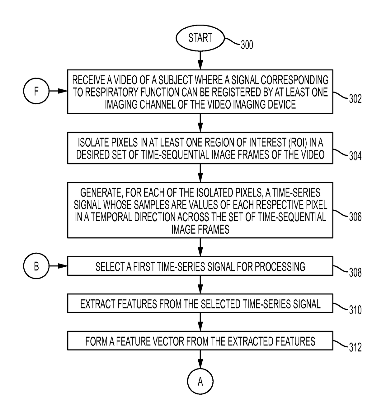
[0042]What is disclosed is a system and method for determining a respiratory pattern for a subject from a video of that subject.

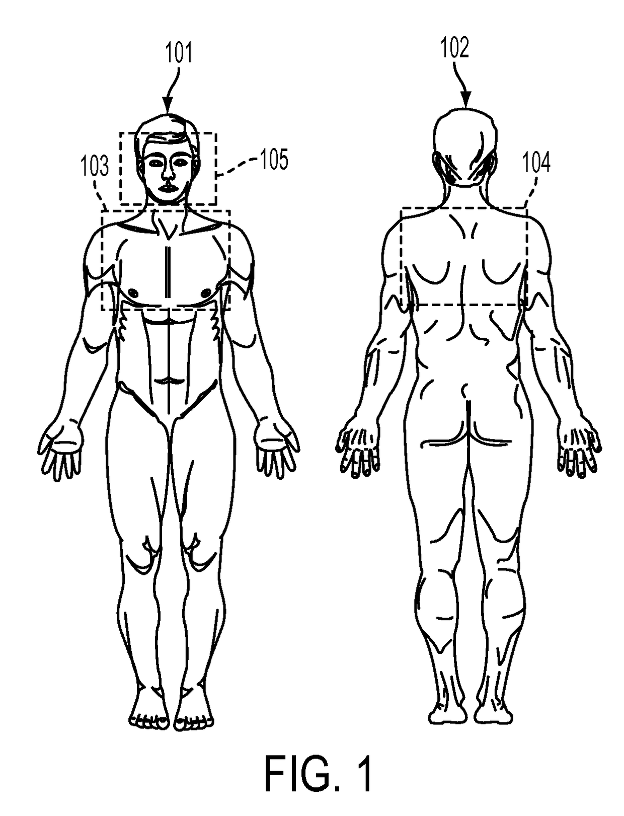
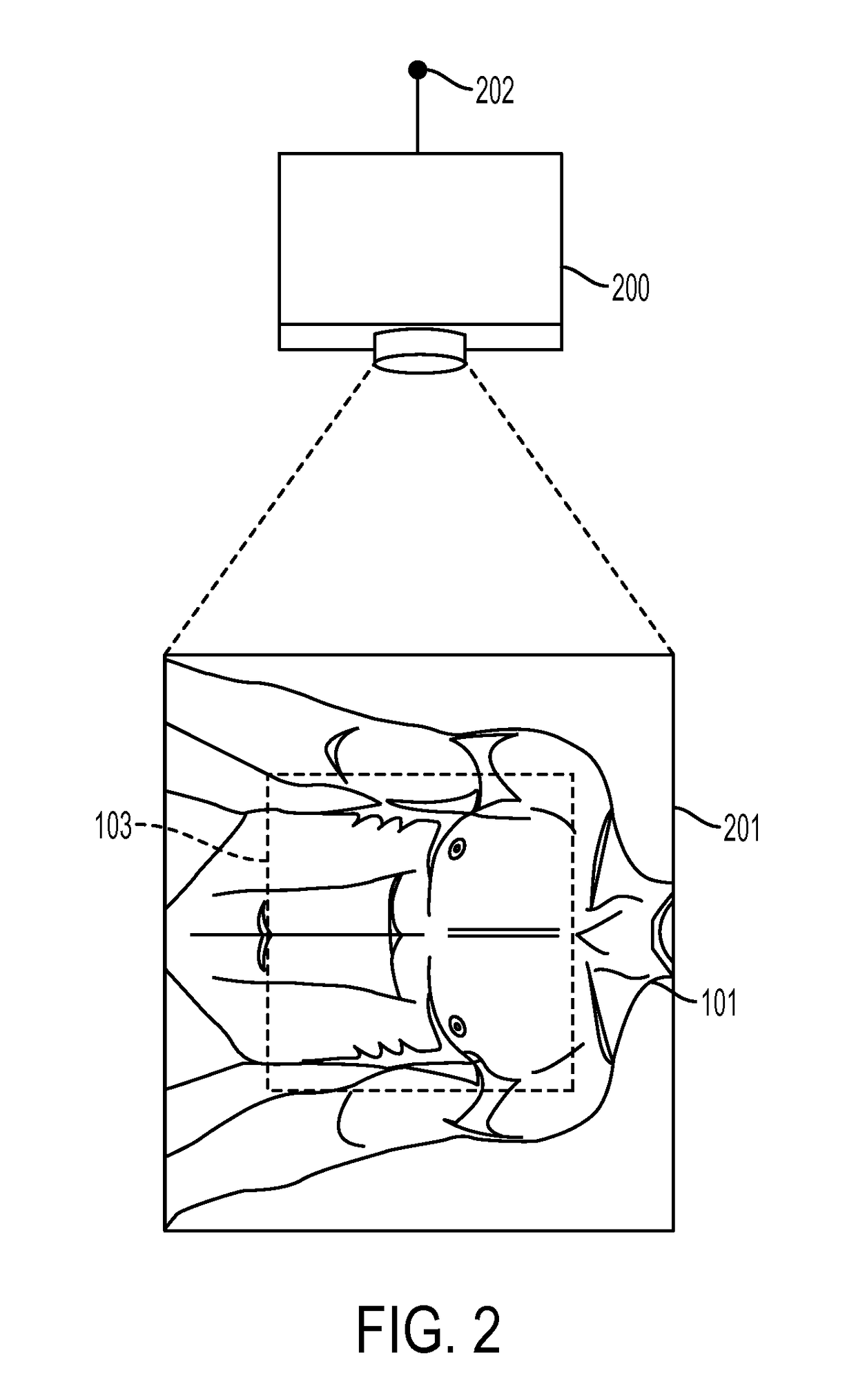
[0043]It should be understood that one of skilled in this art would readily understand various aspects of image frames, pixels, imaging processing, methods for generating a time-series signal from values of pixels obtained from processing batches of image frames as disclosed in several of the incorporated references by Lalit K. Mestha, Edgar Bernal, Beilei Xu and Survi Kyal, and would have a working knowledge of signal processing techniques. Such a person would also readily understand methods for uncovering independent source signal components from a set of observations that are composed of linear mixtures of underlying sources. For a survey, see: “Independent Component Analysis”, Wiley (2001), ISBN-13: 978-0471405405, and “Blind Source Separation: Theory and Applications”, Wiley (2014), ISBN-13: 978-1118679845. One skilled in this art would also have a wor...


PUM


Abstract

What is disclosed is a system and method for determining a subject's respiratory pattern from a video of that subject. One embodiment involves receiving a video comprising N≧2 time-sequential image frames of a region of interest (ROI) of a subject where a signal corresponding to the subject's respiratory function can be registered by at least one imaging channel of a video imaging device. The ROI comprises P pixels. Time-series signals of duration N are generated from pixels isolated in the ROI. Features are extracted from the time-series signals and formed into P-number of M-dimensional vectors. The feature vectors are clustered into K clusters. The time-series signals corresponding to pixels represented by the feature vectors in each cluster are averaged along a temporal direction to obtain a representative signal for each cluster. One of the clusters is selected. A respiratory pattern is determined for the subject based on the representative signal.

Description

TECHNICAL FIELD[0001]The present invention is directed to systems and methods for determining a subject's respiratory pattern from a video of that subject.BACKGROUND[0002]Continuous monitoring of respiratory events is an important clinical requirement as it serves detection of potential fatal physiological events such as acute respiratory failure and pulmonary diseases. Widely used existing methods employ contact sensors (spirometers) that are worn across the chest region of the patients which will produce a signal which is a function of the respiratory events. Such devices, albeit accurate, are associated with discomfort and psychological dependence. Furthermore, remote monitoring of respiratory events can aid applications in monitoring animals in a zoo, in a vet-spot or in situations such as monitoring infected subjects as in Ebola patients where contacts with subjects can lead to similar signs of illness in caretakers and contact tracing becomes extremely cumbersome.[0003]Recentl...

Claims


Application Information

Patent Timeline
Patent Type & Authority Patents(United States)
IPC IPC(8): G06T7/00G06K9/48A61B5/00A61B5/113A61B5/11A61B5/08G06T5/00G06K9/62G06K9/20G06T5/20
CPCG06T7/0012A61B5/0816A61B5/0826A61B5/1128A61B5/1135A61B5/4818A61B5/746G06K9/2054G06K9/481G06K9/6223G06T5/002G06T5/20G06T2207/10016G06T2207/30061G06T5/50G06T7/0016G06T2207/30076A61B5/0013G06V40/10G06T5/70G06T7/20A61B5/0033A61B6/52A61B5/72G06T2210/41G06F18/23213
Inventor PRASAD, PRATHOSH A.MESTHA, LALIT KESHAVMADHU, HIMANSHU J.
Owner XEROX CORP
Learn More