
Hay bale shredder for feeding livestock

a hay bale shredder and livestock technology, applied in the field of hay for feeding livestock, can solve the problems of time and labor intensive manner for distributing hay, small farmers and ranchers can not afford single-use machinery investment, time and labor intensive manner for at least two individuals at the same time, etc., and achieve the effect of reducing the cost of a non-powered vehicle and convenient towing

Active Publication Date: 2017-06-27
STIREWALT DANIEL
View PDF7 Cites 2 Cited by
  • Summary
  • Abstract
  • Description
  • Claims
  • Application Information

AI Technical Summary

Benefits of technology

The device and method described in this patent helps to improve the process of breaking large grass bales into smaller parts. It can be mounted on a vehicle and easily disconnected, allowing for multiple uses. Additionally, the device has a storage support at the rear of the vehicle, which makes it easy to transport and use a spare bale for flaking. The device is designed to handle the weight and bulk of modern bales, and can also carry a second bale to minimize trips for resupply.

Problems solved by technology

Such occurs particularly in the winter or during times when drought or other conditions make pasture grazing by the animal unavailable.
While large agricultural corporations can afford the capital investment for specialized equipment adapted to transport and cut hay bales into smaller increments which are deposited on pastures, small farmers and ranchers generally cannot afford such an investment in single-use machinery.
While such a method allows for the purchase and transport and use of more economical larger bales of hay, it is labor and time intensive for at least two individuals at the same time.
On small farms and ranches where days are long and time is perpetually short to accomplish all the required tasks, such a time and labor intensive manner for distributing hay to the animals, while required by the inability to purchase single-use expensive equipment, is at best ineffective.
Various limitations of the related art are already or will become apparent to those skilled in the art upon a reading and understanding of the specification below and the accompanying drawings.

Method used


Image

  • Hay bale shredder for feeding livestock
  • Hay bale shredder for feeding livestock
  • Hay bale shredder for feeding livestock

Examples


Embodiment Construction

[0034]In this description, the directional prepositions of up, upwardly, down, downwardly, front, back, top, upper, bottom, lower, left, right and other such terms refer to the device as it is oriented and appears in the drawings and are used for convenience only; they are not intended to be limiting or to imply that the device has to be used or positioned in any particular orientation.

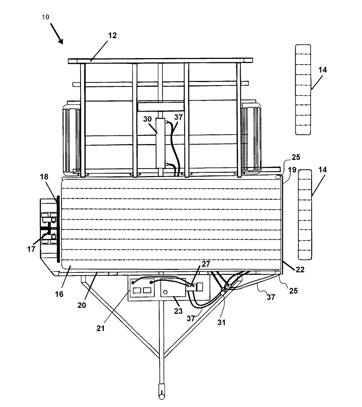
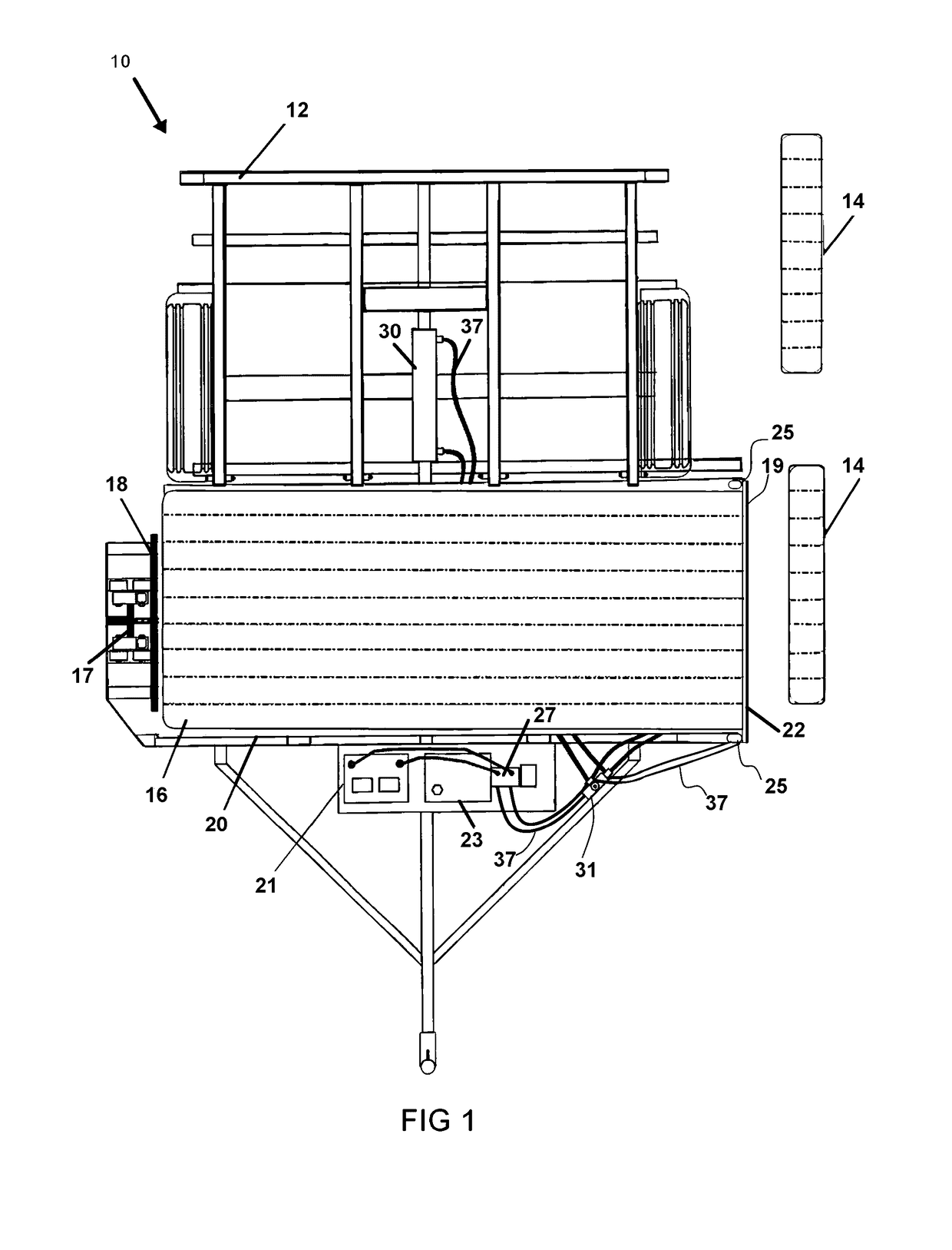
[0035]Now referring to drawings in FIGS. 1-6, wherein similar components are identified by like reference numerals, there is seen in FIG. 1 an overhead plan view of the device 10 mounted upon a wheeled frame herein noted as a vehicle 12 or trailer and showing sections of the hay bale 16 or flakes 14 being sequentially deposited on the ground such as in a pasture.

[0036]Placement of flakes 14 or small sections from the large bale 16 is accomplished by translating the bale 16 using a powered ram 18 positioned to contact the rear of the bale 16. A chain drive 17, is powered by a hydraulic or electric driv...


PUM


Abstract

A hay bale flaking device mountable on a wheeled vehicle such as a trailer is provided. The flaking device employs a ram to translate a hay bale on a ramp, and underneath a cutting blade which at timed intervals cuts flakes of hay from the distal end of the hay bale. The timing and thickness of the flakes may be adjustably controlled. A secondary bale of hay may be carried by the device for positioning upon the ramp subsequent to use of a previous bale to make flakes.

Description

BACKGROUND OF THE INVENTION[0001]1. Field of the Invention[0002]The present invention relates generally to hay for feeding livestock. More particularly, it relates to a vehicle-mounted device configured to render square bales of hay into sequentially positioned small piles of hay on a pasture surface along the route traveled by the vehicle.[0003]2. Prior Art[0004]On modern farms and ranches, hay or grass is the foundation of the diet for all grazing animals such as cattle and horses. Hay can provide as much as 100% of the fodder required for such grazing animals. In many cases, hay is provided as feed to an animal instead of allowing that animal to graze on grasses in a pasture. Such occurs particularly in the winter or during times when drought or other conditions make pasture grazing by the animal unavailable.[0005]Animals that can eat hay vary in the types of grasses which are suitable for their consumption, the ways they consume hay, and how they digest it. Therefore, different ...

Claims


Application Information

Patent Timeline
Patent Type & Authority Patents(United States)
IPC IPC(8): A01F29/00A01D90/00B26D5/20A01K5/00B26D1/08B26D7/06
CPCA01K5/005B26D1/08B26D7/0608B26D5/20A01F29/005Y10S241/605
Inventor STIREWALT, DANIEL
Owner STIREWALT DANIEL
Learn More