
Ultrasound-based localization of client devices with inertial navigation supplement in distributed communication systems and related devices and methods

a distributed communication system and client device technology, applied in the field of distributed communication systems, can solve the problems of inability to provide or determine the location of client devices using global positioning services, other services may be negatively affected or not possible, and gps signals are usually too weak to be received by client devices

Inactive Publication Date: 2017-06-20
CORNING OPTICAL COMM LLC
View PDF490 Cites 0 Cited by
  • Summary
  • Abstract
  • Description
  • Claims
  • Application Information

AI Technical Summary

Benefits of technology

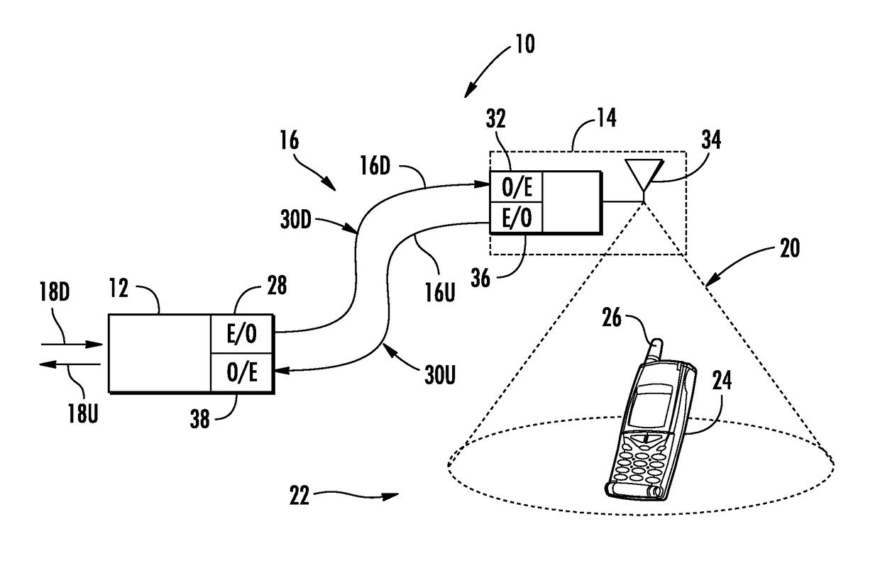
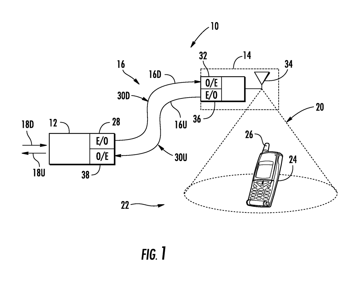
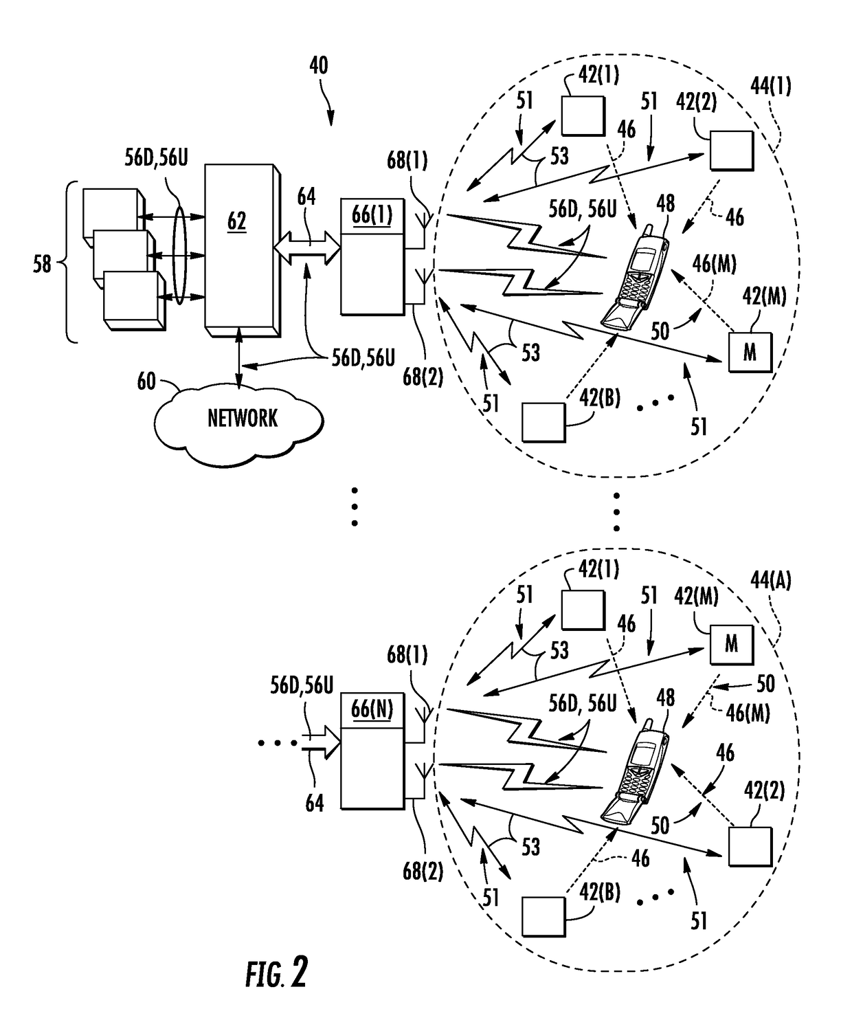
[0013]Embodiments disclosed herein include ultrasound-based localization of client devices in distributed communication systems. Related devices, systems, and methods are also disclosed. In embodiments disclosed herein, a plurality of spatially located ultrasound beacons are provided in known locations within the distributed communication systems. Each of the spatially located ultrasound beacons is configured to emit ultrasound pulses that can be received by client devices in ultrasound communication range of the ultrasound beacons. The client devices are configured to analyze the received ultrasound pulses from the plurality of ultrasound beacons to determine their time-difference of arrivals at the client device. As a result, the client devices can determine their relative distance to ultrasound beacons in a distributed communication system. In certain embodiments, a master ultrasound beacon is provided that encodes location information in a second channel with emitted ultrasound pulses received by the client devices that can be used with the determined relative distance to determine location of the client device in the distributed communication system.
[0014]The distributed communication systems employing ultrasound beacons can facilitate the determining and / or providing of location information to client devices, including wireless client devices that may not otherwise be able to receive, for example, GPS information from GPS satellites. Providing location information to client devices inside a building or other location may make location-based services possible (e.g., emergency 911 (E911) services) for the client devices.
[0015]Use of ultrasound pulses by a client device to determine its location in a distributed communication system can provide greater resolution (e.g., sub-meter resolution) in location determination. Increased resolution results from the lower velocity of sound (as opposed to light or radio-frequency signals), which translates into lessened requirements for time resolution in ultrasound pulse measurements. Ultrasound waves experience strong attenuation in buildings walls, ceilings, and floors, thus the ultrasound beacons can be strategically placed to allow client devices to avoid detection of ultrasound waves from other ultrasound beacons not located in proximity to the client devices (e.g., on a different floor). Use of ultrasound pulses to facilitate location determination using time-difference of arrival can also avoid the need to synchronize the clock of the client device.

Problems solved by technology

Other services may be negatively affected or not possible due to the indoor environment.
If a client device is located indoors, techniques such as global positioning services (GPS) may not be effective at providing or determining the location of the client device.
Indoors, GPS signals are usually too weak to be received by client devices.
Further, triangulation and / or trilateration techniques from the outside network may not be able to determine the location of client devices.
However, use of existing wireless data signals may only be accurate to down to a resolution of still a relatively large distance (e.g., ten meters) since the client devices may receive wireless data signals from wireless data devices not in close proximity to the client devices.
Thus, determining location of client devices at lower resolution distances (e.g., less than ten (10) meters, floor level in a building, etc.) using wireless communication signals transmitted from existing wireless data devices may not be possible without providing additional, greater densities of these wireless data devices at greater cost and complexity.

Method used


Image

  • Ultrasound-based localization of client devices with inertial navigation supplement in distributed communication systems and related devices and methods
  • Ultrasound-based localization of client devices with inertial navigation supplement in distributed communication systems and related devices and methods
  • Ultrasound-based localization of client devices with inertial navigation supplement in distributed communication systems and related devices and methods

Examples


Embodiment Construction

[0013]Embodiments disclosed herein include ultrasound-based localization of client devices in distributed communication systems. Related devices, systems, and methods are also disclosed. In embodiments disclosed herein, a plurality of spatially located ultrasound beacons are provided in known locations within the distributed communication systems. Each of the spatially located ultrasound beacons is configured to emit ultrasound pulses that can be received by client devices in ultrasound communication range of the ultrasound beacons. The client devices are configured to analyze the received ultrasound pulses from the plurality of ultrasound beacons to determine their time-difference of arrivals at the client device. As a result, the client devices can determine their relative distance to ultrasound beacons in a distributed communication system. In certain embodiments, a master ultrasound beacon is provided that encodes location information in a second channel with emitted ultrasound ...


PUM


Abstract

Spatially located ultrasound beacons are provided in known locations within a distributed communication system. The ultrasound beacons are configured to emit ultrasound pulses that can be received by client devices in ultrasound communication range of the beacons. The client devices are configured to analyze the received ultrasound pulses from the beacons to determine their time-difference of arrival and as a result, their location(s) within the distributed communication system. The client devices comprise inertial navigation systems (INS) that calculate client device location as the client device moves, and when received ultrasound signals are below a predefined threshold.

Description

PRIORITY APPLICATION[0001]This application is a continuation of International Application No. PCT / US13 / 43107 filed on May 29, 2013 which claims the benefit of priority to U.S. Provisional Application No. 61 / 652,575, filed on May 29, 2012, both applications being incorporated herein by reference.BACKGROUND[0002]Field of the Disclosure[0003]The technology of the disclosure relates to distributed communication systems, and in particular to providing devices, systems, and methods to allow determination of the location of client devices within distributed communication systems.[0004]Technical Background[0005]Wireless communication is rapidly growing, with ever-increasing demands for high-speed mobile data communication. “Wireless fidelity” or “WiFi” systems and wireless local area networks (WLANs) are now deployed in many different types of areas. Distributed antenna systems communicate with wireless devices called “clients,”“client devices,” or “wireless client devices,” which must resi...

Claims


Application Information

Patent Timeline
Patent Type & Authority Patents(United States)
IPC IPC(8): G01S5/26G01S5/18G01S1/76G01S5/02G01S1/80
CPCG01S5/0257G01S5/0263G01S5/26G01S5/18G01S1/76G01S1/802
Inventor NEUKIRCH, ULRICH WILHELM HEINZSABAN, OFER
Owner CORNING OPTICAL COMM LLC
Learn More