Canopy shelter link point

a link point and canopy frame technology, applied in tents/canopies, construction, building types, etc., can solve the problems of canopy frame bending or failure, reduce and create unwanted flexibility in the canopy frame, and produce additional stresses at each link point. , to achieve the effect of reducing the structural integrity of the fram

Active Publication Date: 2017-06-20
SHELTERLOGIC
View PDF480 Cites 14 Cited by
  • Summary
  • Abstract
  • Description
  • Claims
  • Application Information

AI Technical Summary

Benefits of technology

[0009]One aspect of the present invention is the realization that the spacer placed between the cross members at the link point creates a space between the cross members, allowing them to bend relative to one another, creating unwanted flexibility in the canopy frame and producing additional stresses at each link point. This flexibility reduces the structural integrity of the frame and sometimes leads to canopy frame bending or failure. Thus, there exists a need for an improved link point design.
[0010]One non limiting embodiment of the present invention includes an extended cross member providing an extended overlapping distance and decreasing the amount of misalignment possible and thus the misalignment angle between the left cross member and right cross member when the canopy frame is in an expanded state.
[0011]Another non limiting embodiment of the present invention includes an enlarged head cross member insert configured to bridge some or all of the gap between the left cross member and right cross member, thus decreasing the amount of misalignment possible and thus the misalignment angle between the left cross member and right cross member when the canopy frame is in an expanded state.

Problems solved by technology

This flexibility reduces the structural integrity of the frame and sometimes leads to canopy frame bending or failure.

Method used


Image

  • Canopy shelter link point
  • Canopy shelter link point
  • Canopy shelter link point

Examples


Embodiment Construction

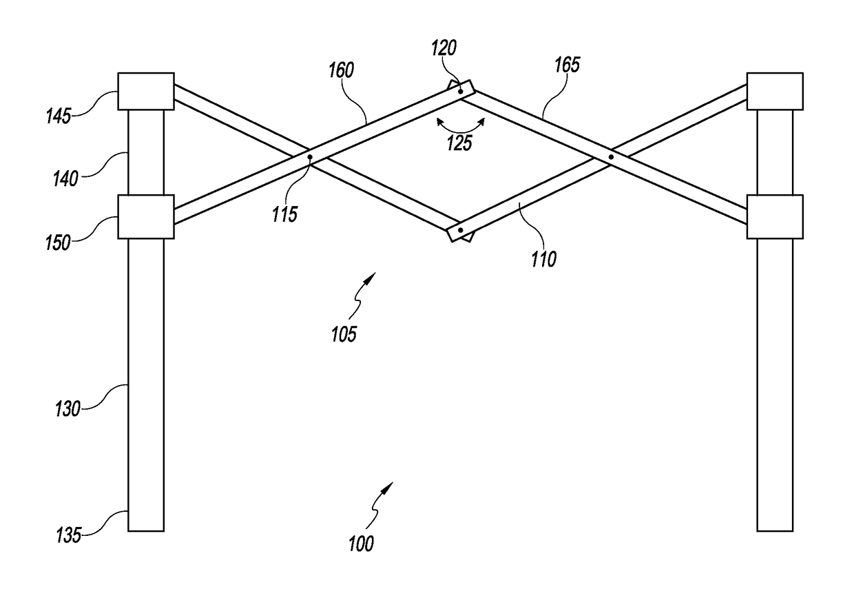
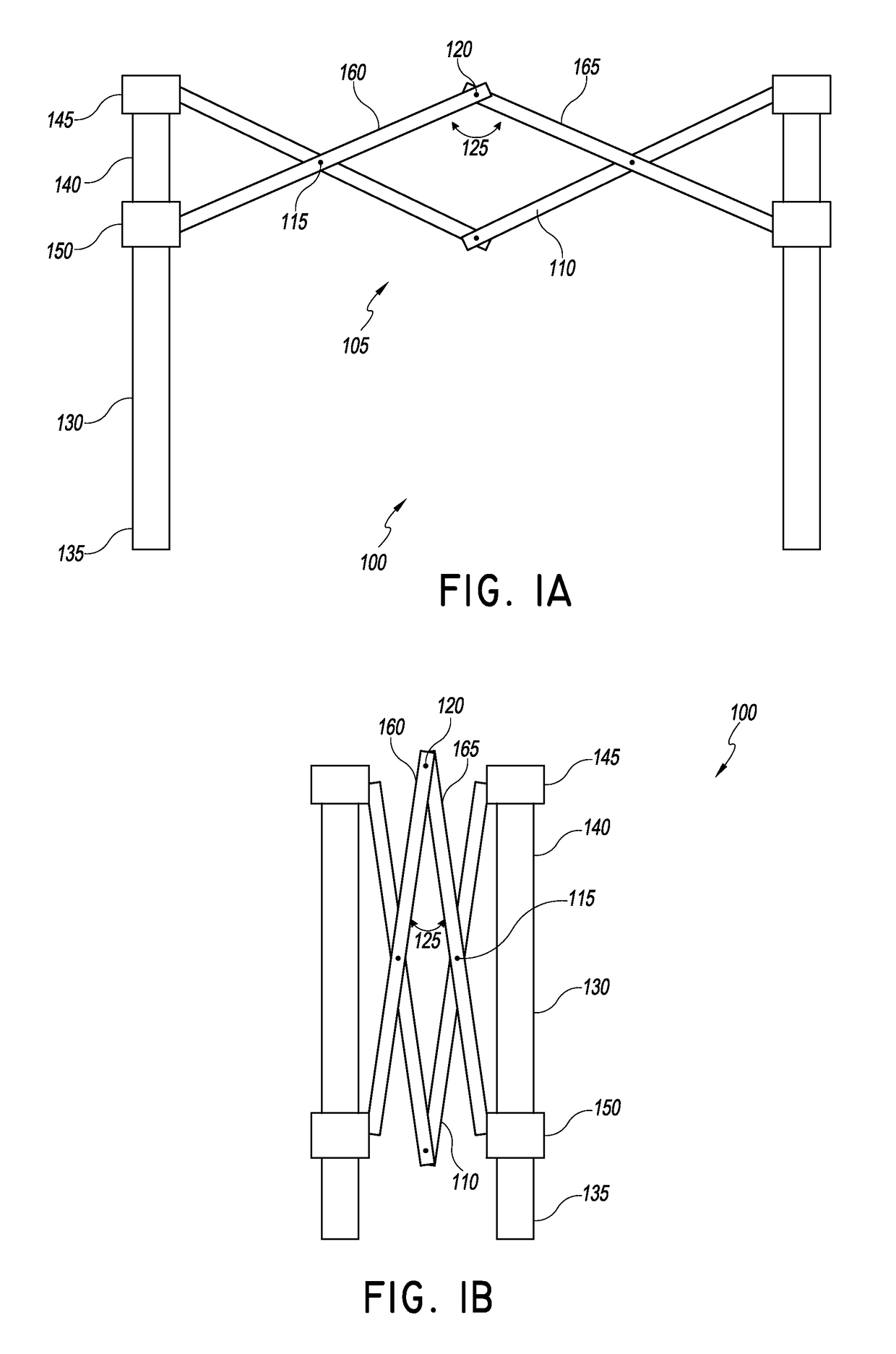
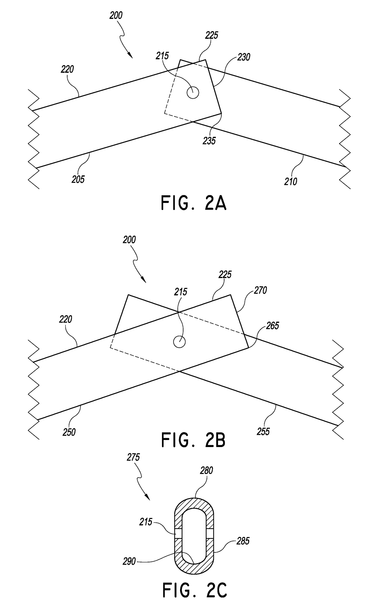
[0052]In the following detailed description, reference is made to the accompanying drawings, which form a part of the present disclosure. The illustrative embodiments described in the detailed description, drawings, and claims are not meant to be limiting. Other embodiments may be utilized, and other changes may be made, without departing from the spirit or scope of the subject matter presented here. It will be readily understood that the aspects of the present disclosure, as generally described herein, and illustrated in the Figures, can be arranged, substituted, combined, and designed in a wide variety of different configurations, all of which are explicitly contemplated and form part of this disclosure. For example, a system or device may be implemented or a method may be practiced using any number of the aspects set forth herein. In addition, such a system or device may be implemented or such a method may be practiced using other structure, functionality, or structure and functi...


PUM


Abstract

A canopy shelter link point for increased structural integrity particularly when subject to bending forces about the link point. The canopy shelter link point can include an increased overlap distance between two cross members, reduced spacing between adjacent cross members, and / or extension features located about an end of the cross members to reduce the misalignment angle between two cross members. Such features can be provided using spacers, inserts to be inserted into a cross member and / or sleeves to be placed around the cross member. A reduction in the misalignment angle can reduce the amount of bending forces about the link point.

Description

INCORPORATION BY REFERENCE TO PRIORITY APPLICATION[0001]The present application claims priority to U.S. Provisional Application No. 61 / 734,887 filed Dec. 7, 2012, entitled CANOPY SHELTER LINK POINT, the entire contents of which are hereby expressly incorporated by reference herein and made a part of the present disclosure.BACKGROUND OF THE INVENTIONS[0002]Field of the Invention[0003]The present invention relates to collapsible canopy frames and, in particular, canopy frames having improved link points.[0004]Description of the Related Art[0005]Canopy shelters with collapsible frames are commonly used to provide portable shelter for outdoor activities such as camping, picnicking, parties, weddings, and more. Such collapsible canopy shelters typically comprise a canopy cover and a canopy frame configured to stand alone when in an expanded or deployed state and to collapse into a collapsed state for storage and transport.[0006]While conventional canopy shelters are useful for a variety ...

Claims


Application Information

Patent Timeline
Patent Type & Authority Patents(United States)
IPC IPC(8): E04H15/50
CPCE04H15/50
Inventor LOVLEY, II, JACK B.
Owner SHELTERLOGIC
Why Eureka
Try Eureka