Liquid sensor comprising first and second electrodes opposing each other

a liquid sensor and electrode technology, applied in the field of liquid sensor comprising a first electrode and a second electrode, can solve the problems of liquid being inhibited from staying inside the storage space, and it is difficult to properly detect the property of the liquid with the electrodes

Inactive Publication Date: 2017-06-13
AISAN IND CO LTD
View PDF17 Cites 1 Cited by
  • Summary
  • Abstract
  • Description
  • Claims
  • Application Information

AI Technical Summary

Benefits of technology

[0006]In the foregoing configuration, liquid flows into the storage space through one of the first communication opening and the second communication opening and flows out of the storage space through the other one of the first communication opening and the second communication opening. Since the first communication opening is provided above the storage space, gas in the storage space is discharged out of the storage space through the first communication opening. Furthermore, since the second communication opening is provided below the first communication opening and the opening direction of the first communication opening is different from the opening direction of the second communication opening, the liquid flows from one of the first communication opening and the second communication opening to the other one of the first communication opening and the second communication opening in such a manner as to spread across the storage space. As a result of this, the liquid may be inhibited from staying inside of the storage space. This causes gas in the liquid to be discharged out of the storage space by being pushed out by the liquid. According to this configuration, the gas out of the clearance between electrodes may be properly discharged.

Problems solved by technology

In a case where liquid between electrodes contains many bubbles, it is difficult to properly detect a property of the liquid with the electrodes.
As a result of this, the liquid may be inhibited from staying inside of the storage space.

Method used


Image

  • Liquid sensor comprising first and second electrodes opposing each other
  • Liquid sensor comprising first and second electrodes opposing each other
  • Liquid sensor comprising first and second electrodes opposing each other

Examples


first embodiment

[0058](First Embodiment)

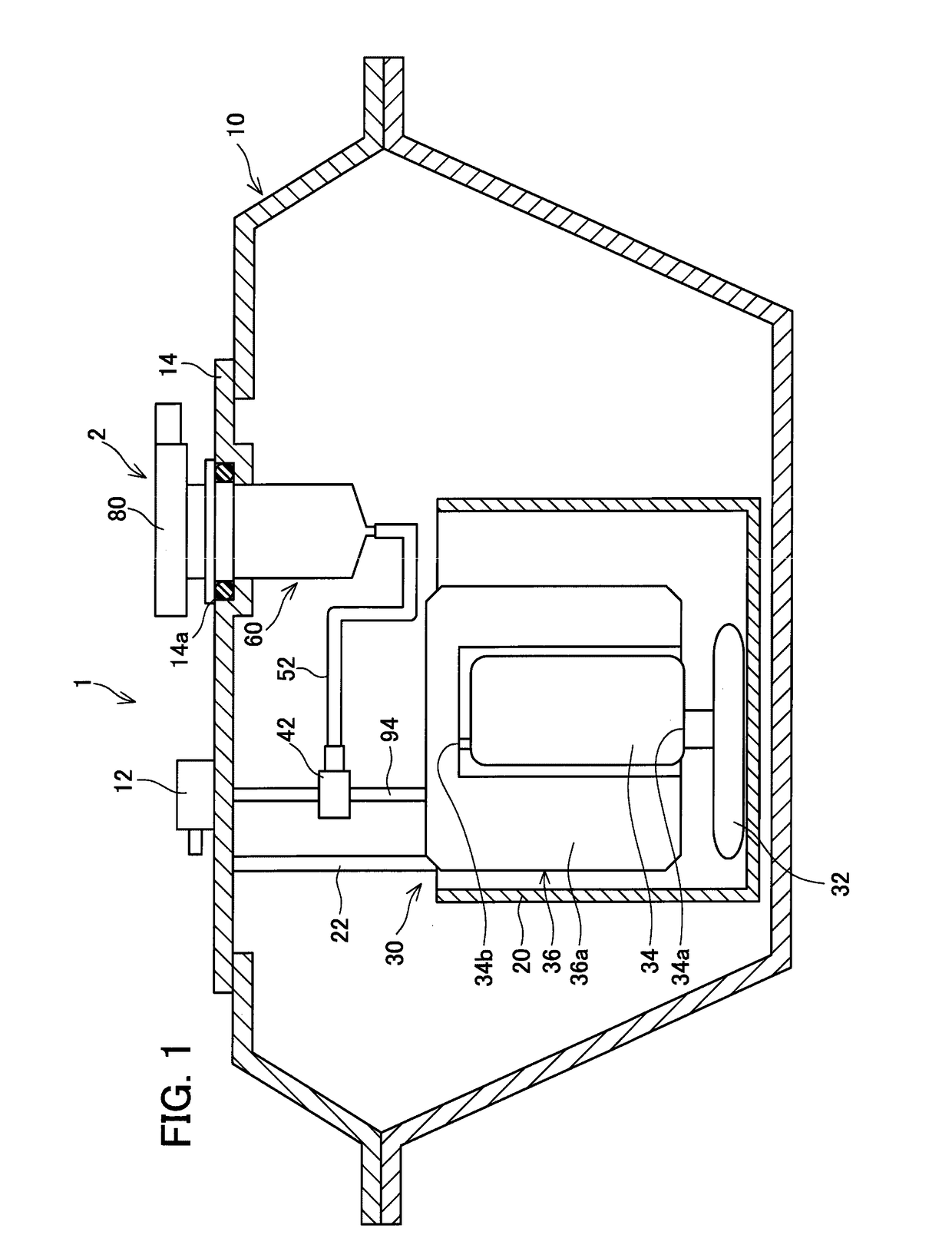
[0059]A fuel feeding unit 1 of the present embodiment is mounted in an automobile, and feeds fuel to an engine (not illustrated). The fire supplying unit 1 includes a fuel tank 10, a fuel pump unit 30, and a sensor device 2. The fuel tank 10 retains gasoline or mixed fuel of gasoline and ethanol.

[0060]The fuel pump unit 30 includes a low-pressure filter 32, a pump body 34, a high-pressure filter 36, a reserve cup 20, a pressure regulator 42, and a discharge port 12. The low-pressure filter 32, the pump body 34, the high-pressure filter 36, the reserve cup 20, and the pressure regulator 42 are disposed inside of the fuel tank 10. The pump body 34 sucks the fuel stored in the fuel tank 10 through a suction opening 34a of the pump body 34 and pressurizes the fuel inside of the pump body 34. Then, the pump body 34 forces the pressurized fuel into a case 36a of the high-pressure filter 36 through an outlet 34b of the pump body 34.

[0061]The low-pressure filter 32 i...

second embodiment

[0095](Second Embodiment)

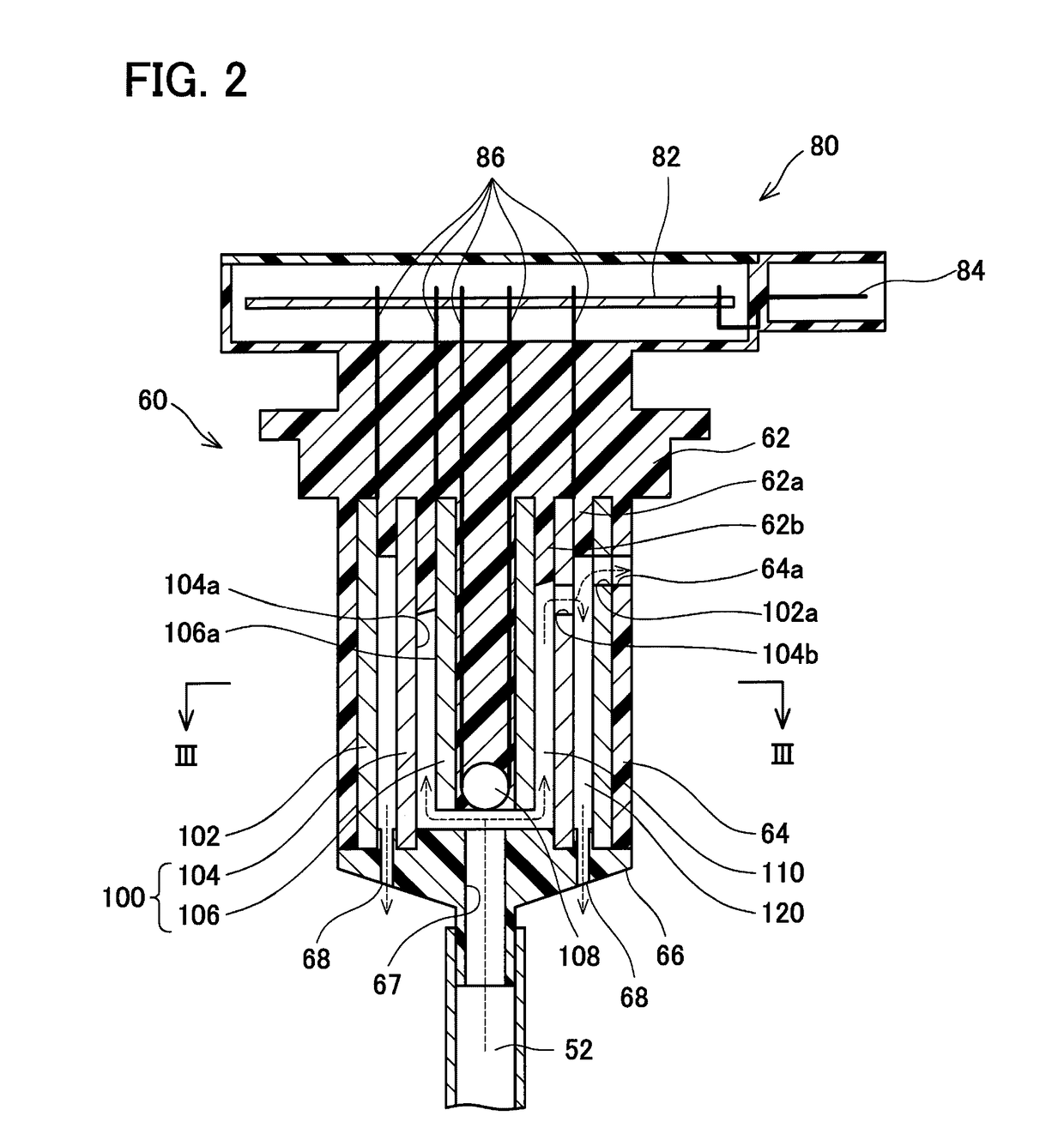
[0096]Points of difference between a liquid property sensor 260 of the second embodiment and the liquid property sensor 60 of the first embodiment are described with reference to FIG. 14. Components that are the same as those of the first embodiment are given the same reference signs as those of the first embodiment.

[0097]The liquid property sensor 260 includes an upper wall 62, a peripheral wall 264, a bottom wall 66, an electrode pair 100, and a thermistor 108. It should be noted that the liquid property sensor 260 does not include an electrode 102.

[0098]The peripheral wall 264 is disposed with a clearance between the peripheral wall 264 and the outer circumferential surface of the electrode 104. Otherwise, the peripheral wall 264 is the same in configuration as the peripheral wall 64. The support wall 62a disposed on the lower surface of the upper wall 62 is disposed between the electrode 104 and the peripheral wall 264. The storage space 120 is defined b...

third embodiment

[0099](Third Embodiment)

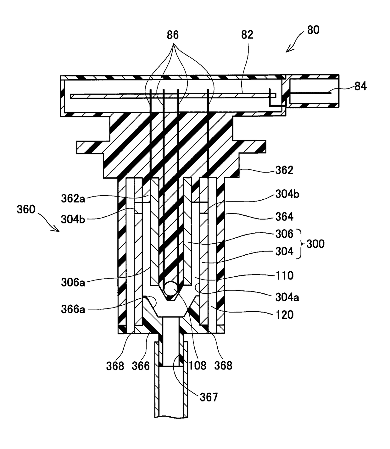
[0100]Points of difference between a liquid property sensor 360 of the third embodiment and the second embodiment are described with reference to FIG. 15. Components that are the same as those of the second embodiment are given the same reference signs as those of the second embodiment. The liquid property sensor 360 includes an upper wall 362, a peripheral wall 364, a bottom wall 366, an electrode pair 300, and a thermistor 108.

[0101]The electrode pair 300 includes electrodes 304 and 306. As compared with the electrode 106, the electrode 306 has its lower portion becoming gradually narrower toward a lower position. Otherwise, the electrode 306 is the same in configuration as the electrode 106. This configuration allows the thermistor 108 to be closer to the liquid inside of the storage space 110. As a result of this, the temperature of the fuel inside of the storage space 110 can be more properly detected with the thermistor 108. The electrode 304 has two co...


PUM

PropertyMeasurementUnit
frequencyaaaaaaaaaa
electrically conductiveaaaaaaaaaa
concentrationaaaaaaaaaa

Abstract

A liquid sensor may comprise a first electrode, a second electrode disposed inside the first electrode, and a partition wall comprising a surface defining a storage space with a first opposing surface of the first electrode and a second opposing surface of the second electrode. One of the first electrode, the second electrode and the partition wall may comprise a first communication opening communicating an inside of the storage space and an outside of the storage space and disposed at an upper portion of the storage space. One of the first electrode, the second electrode and the partition wall may comprise a second communication opening communicating the inside of the storage space and the outside of the storage space and disposed lower than the first communication opening. An opening direction of the first communication opening may be different from an opening direction of the second communication opening.

Description

CROSS-REFERENCE TO RELATED APPLICATION[0001]This application claims priority to Japanese Patent Application No. 2013-206648 filed on Oct. 1, 2013, the contents of which are hereby incorporated by reference into the present application.TECHNICAL FIELD[0002]The present application discloses a liquid sensor comprising a first electrode and a second electrode opposing the first electrode.DESCRIPTION OF RELATED ART[0003]Japanese Patent Application Publication, No. 2012-108030 discloses a fuel sensor configured to detect a concentration of ethanol in fuel. The fuel sensor includes an outer electrode and an inner electrode. The outer electrode is disposed on a fuel passage. The inner electrode is disposed inside of the outer electrode. The outer electrode includes a communication opening through which fuel flowing through the fuel passage is introduced into a space between the outer electrode and the inner electrode. The fuel sensor is configured to detect the concentration of ethanol from...

Claims


Application Information

Patent Timeline
Patent Type & Authority Patents(United States)
IPC IPC(8): G01N33/22G01N33/28
CPCG01N33/2852
Inventor KATO, NOBUHIRO
Owner AISAN IND CO LTD
Why Eureka
Try Eureka