
Ultrasonic surgical system and method

a surgical system and ultrasonic technology, applied in ultrasonic/sonic/infrasonic diagnostics, surgery, tomography, etc., can solve the problems of inability to accurately predict the effect of the operation, the surgeon's skill is still required to perform certain surgical steps, and the surgeon's inability to perform a plurality of surgical tasks in a well-coordinated manner,

Active Publication Date: 2017-06-13
CILAG GMBH INT
View PDF54 Cites 1039 Cited by
  • Summary
  • Abstract
  • Description
  • Claims
  • Application Information

AI Technical Summary

Benefits of technology

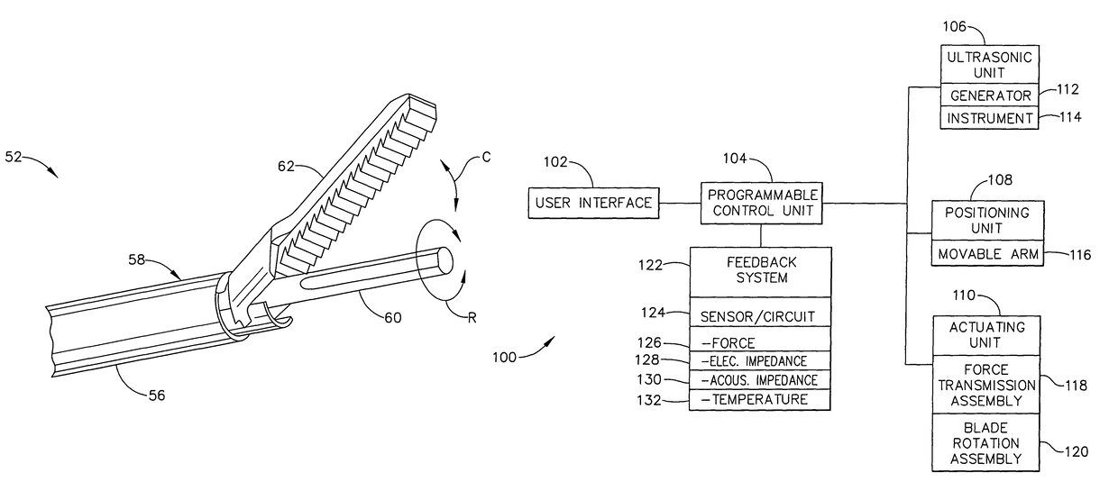
The ultrasonic surgical system in this patent includes an ultrasonic generator, an instrument with an ultrasonic end effector, a positioning unit for holding the instrument, and a control unit programmed with a surgical subroutine for performing various surgical tasks. The system can automatically perform the surgical tasks according to the programmed subroutine and also process feedback signals from sensors in the instrument and control unit to respond to the surgical subroutine. Another embodiment includes an energy-based clamp coagulator with temperature sensors for monitoring the temperature of patient tissue. Overall, this ultrasonic surgical system and method offer improved precision and efficiency in surgical procedures.

Problems solved by technology

Despite such advances in surgical technologies, however, considerable skill is still required by surgeons to perform particular steps of some surgical procedures.
Obviously, some of this sensory feedback is greatly diminished if the surgeon is using a robotic surgical system and separated from the patient.
Clearly, it may be very difficult, if not impossible, for a surgeon to perform a plurality of surgical tasks in a well-coordinated manner, wherein the tasks may include, for example, sweeping the ultrasonic blade on tissue, rotating the blade, pulsing the clamping force and applying ultrasonic energy at various power levels.

Method used


Image

  • Ultrasonic surgical system and method
  • Ultrasonic surgical system and method
  • Ultrasonic surgical system and method

Examples


Embodiment Construction

[0031]The following description pertains to an ultrasonic surgical system and method for performing a surgical procedure according to an automated surgical subroutine. The system and method may be particularly useful for ultrasonically cutting and coagulating soft tissue in a patient, but the system and method may also be adapted to other types of surgical procedures. A surgeon may initiate the surgical subroutine during a surgical procedure to perform a plurality of surgical tasks simultaneously and / or in a coordinated manner, wherein the surgical tasks may include sweeping an ultrasonic blade of the instrument against the tissue, rotating the blade, actuating a clamping element, applying various power levels of ultrasonic energy and obtaining feedback signals associated with the performance of the instrument.

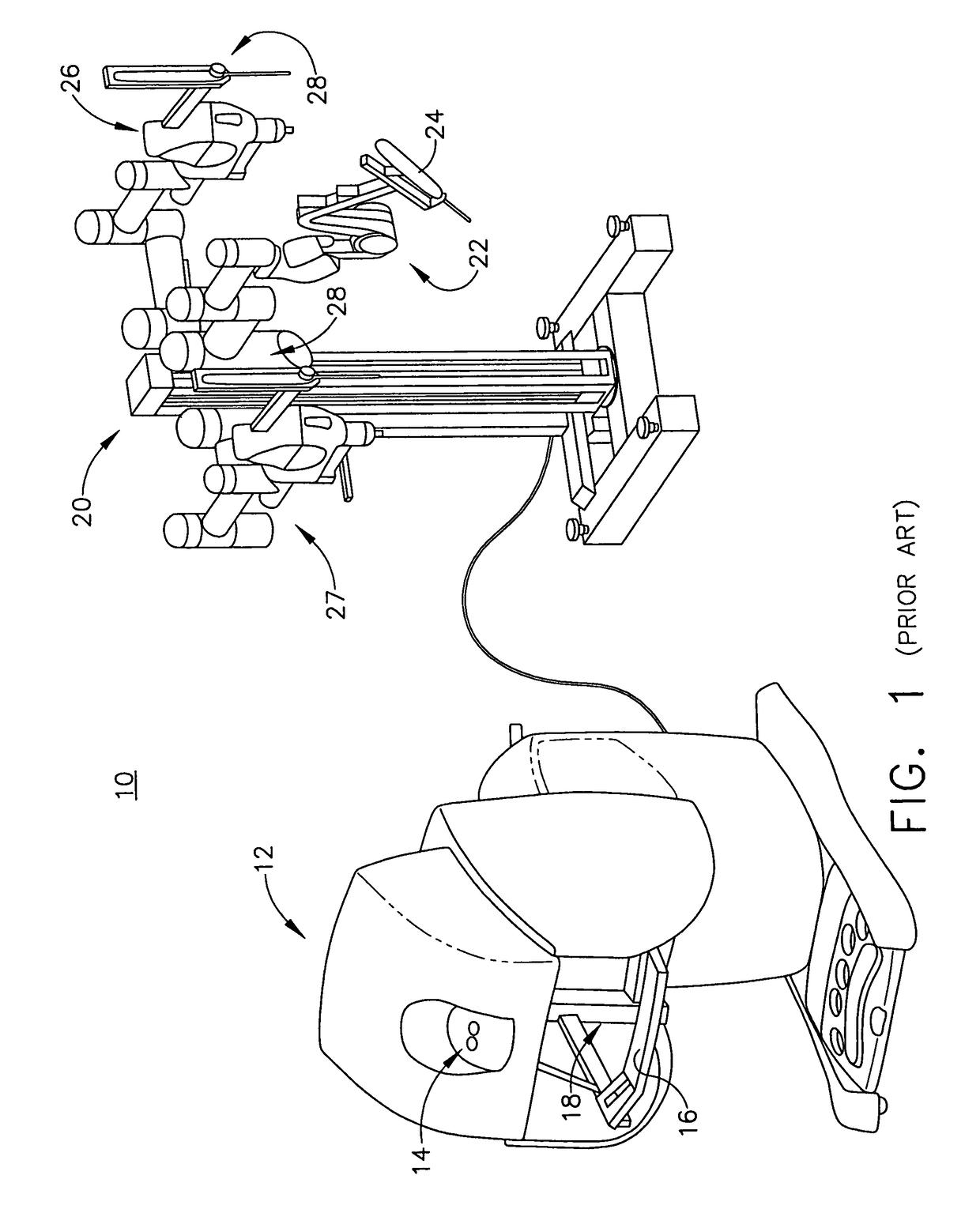
[0032]The ultrasonic surgical system to be described herein may include or be used in conjunction with a surgical robotic apparatus such as the prior art DA VINCI system (Intu...


PUM


Abstract

An ultrasonic surgical system has an ultrasonic unit including an instrument operatively connected to an ultrasonic generator, wherein the instrument has an ultrasonic end effector on the distal end of a shaft. The system further includes a positioning unit including a movable arm adapted for releasably holding the instrument, whereby an operator may direct the positioning unit to position the end effector at a surgical site inside a body cavity of a patient for performing a plurality of surgical tasks. The system further includes a control unit operatively connected to the ultrasonic and positioning units, wherein the control unit is programmable with a surgical subroutine for performing the surgical tasks. The system further includes a user interface operatively connected to the control unit for initiating an operative cycle of the surgical subroutine such that the surgical tasks are automatically performed during the operative cycle.

Description

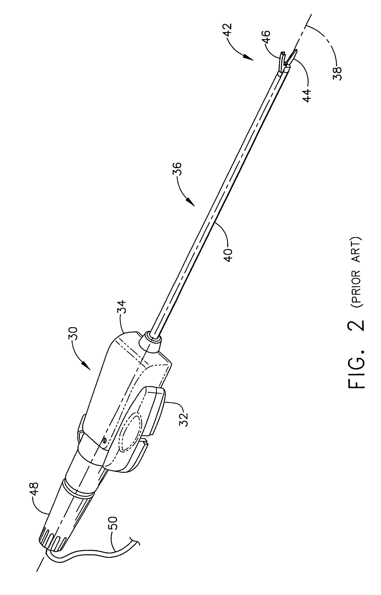
FIELD OF THE INVENTION[0001]The present application relates to ultrasonic surgical instruments and, more particularly, to ultrasonic surgical instruments having end effectors for cutting and coagulating tissue. The present application also relates to robotic surgical systems and, more particularly, to robotic surgical systems used with ultrasonic surgical instruments.BACKGROUND OF THE INVENTION[0002]Surgeons use ultrasonic instruments in surgery to cut and coagulate tissue. Piezoelectric elements are electrically excited at a resonant frequency of an ultrasonic instrument to create vibrations that are transmitted through a resonator and amplified to produce a mechanical, standing wave vibration of the same frequency. An ultrasonic transmission assembly of the instrument has an elongated, transmission waveguide that transmits this vibration to an end effector (e.g., cutting blade) on the distal tip of the instrument. An example of an ultrasonic surgical instrument is the Harmonic Sca...

Claims


Application Information

Patent Timeline
Patent Type & Authority Patents(United States)
IPC IPC(8): A61B17/32A61B34/00A61B34/32A61B34/30A61B34/37A61B17/00
CPCA61B17/320092A61B34/30A61B34/32A61B34/37A61B34/70A61B34/71A61B2017/00022A61B2017/00026A61B2017/00084A61B2017/320095A61B2017/320093A61B2017/320094A61B2017/00199
Inventor HOUSER, KEVIN L.DONOFRIO, WILLIAM T.STULEN, FOSTER B.
Owner CILAG GMBH INT
Learn More