One wire parasite power switch control circuit

a power switch control circuit and parasite technology, applied in the direction of pulse circuits, multiple input and output pulse circuits, oscillator generators, etc., can solve the problems of small current leakage, unnecessary power loss of electronic devices, etc., to prevent power loss, prevent power loss, and high impedance

Active Publication Date: 2017-05-23
MAXIM INTEGRATED PROD INC
View PDF3 Cites 2 Cited by
  • Summary
  • Abstract
  • Description
  • Claims
  • Application Information

AI Technical Summary

Benefits of technology

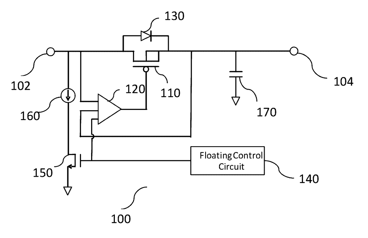
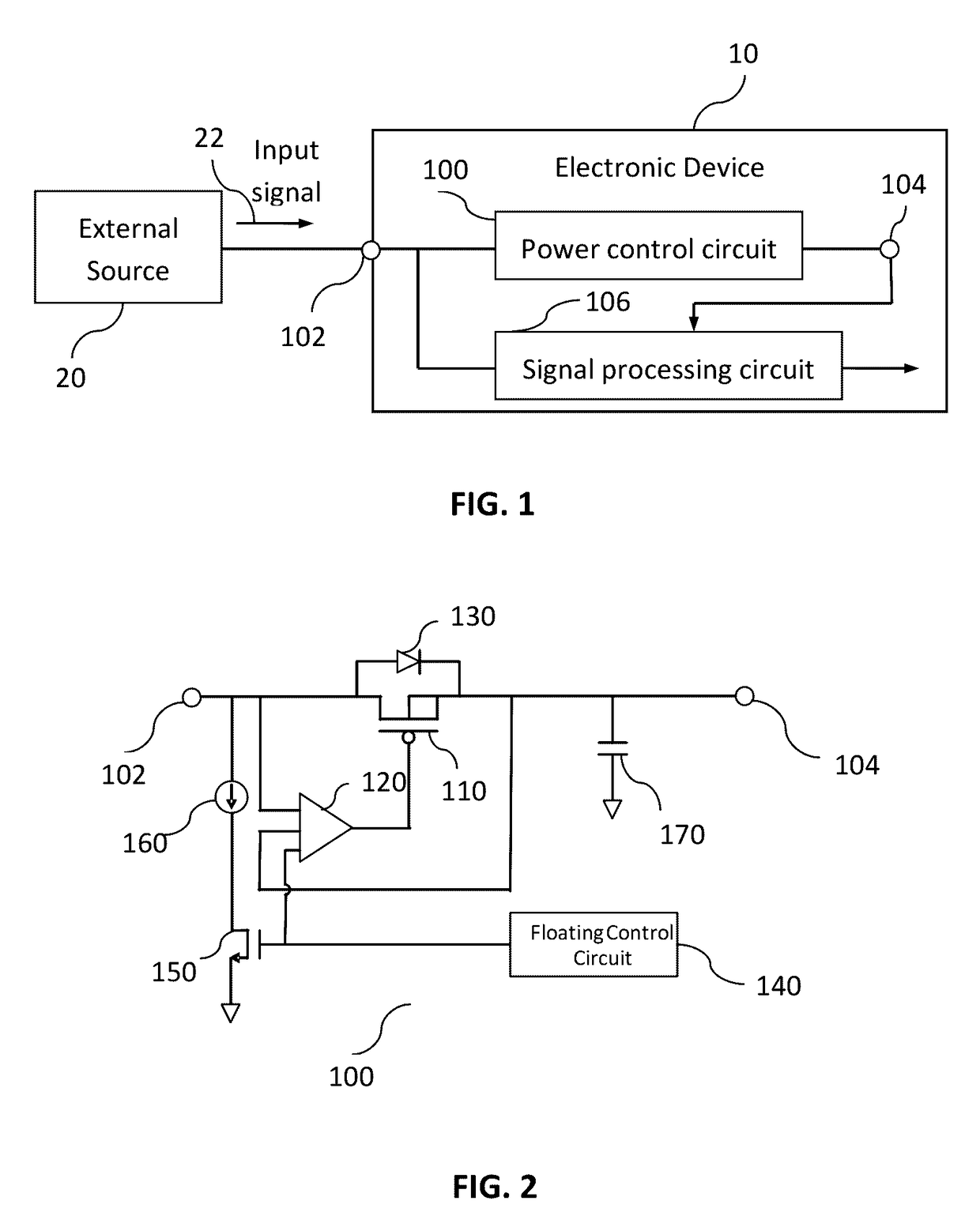
[0011]In certain operation conditions, the input node is floating and a small current leakage may happen, even though the internal input node may have high impedance to ground. The small leakage current may cause unnecessary power loss from the electronic device, especially when the controllable switch is still ON. When the current leakage is below a certain threshold, the comparator may not identify the voltage difference between the input node and the power node and will not switch OFF the controllable switch. Therefore, the power loss is therefore not prevented. To prevent power loss under the above scenario, a watchdog circuit is incorporated within the control circuit to periodic generate a small pulse to enable a small current source pulling the external node down. During normal operation, the external power is much stronger than the pulling-down current source, so that the operation will not be affected. When the input node is floating, the pulling-down current can induce a quick voltage drop to enable the comparator turning off the controllable switch, and thus prevent power loss.
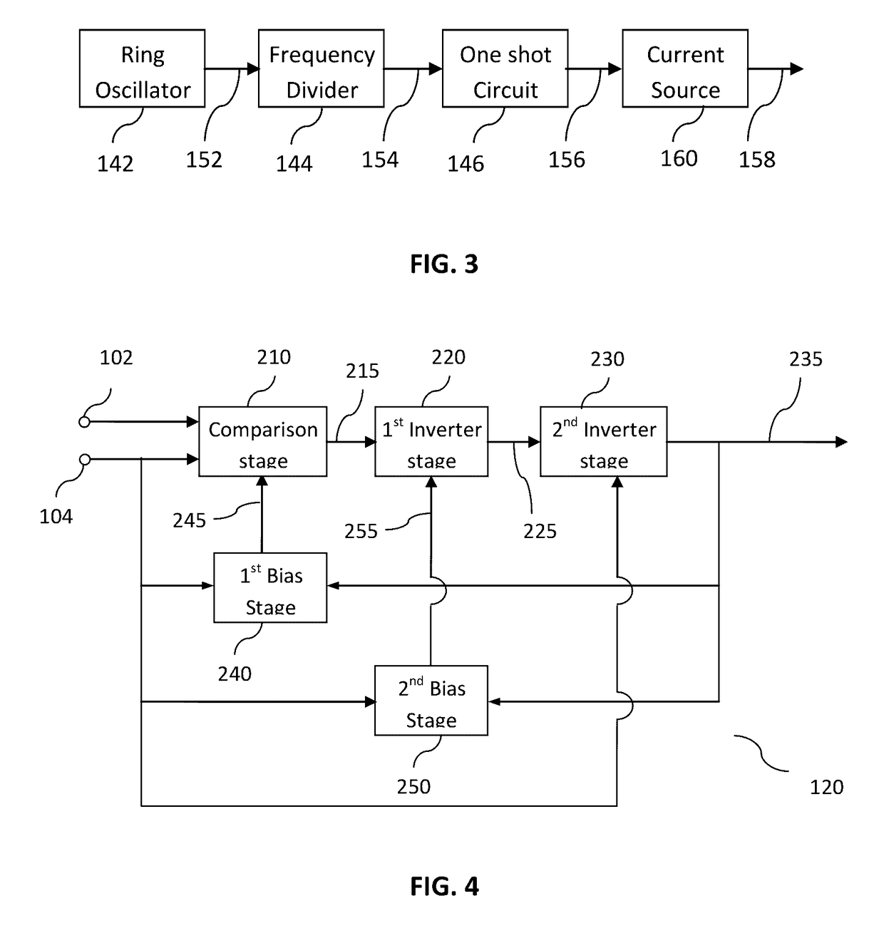
[0012]In some embodiments, the watchdog circuit has a ring oscillator designed to provide clock signal for the generation of periodic current pulses. A frequency divider may be incorporated to lower the frequency of the clock prevent excessive power consumption from the periodic current pulses. The ON period of the pulses may be adjusted for optimized switch control implementation with minimized power consumption.

Problems solved by technology

In certain operation conditions, the input node is floating and a small current leakage may happen, even though the internal input node may have high impedance to ground.
The small leakage current may cause unnecessary power loss from the electronic device, especially when the controllable switch is still ON.

Method used


Image

  • One wire parasite power switch control circuit
  • One wire parasite power switch control circuit
  • One wire parasite power switch control circuit

Examples


Embodiment Construction

[0021]In the following description, for the purpose of explanation, specific details are set forth in order to provide an understanding of the present invention. The present invention may, however, be practiced without some or all of these details. The embodiments of the present invention described below may be incorporated into a number of different electrical components, circuits, devices, and systems. Structures and devices shown in block diagram are illustrative of exemplary embodiments of the present invention and are not to be used as a pretext by which to obscure broad teachings of the present invention. Connections between components within the figures are not intended to be limited to direct connections. Rather, connections between components may be modified, re-formatted, or otherwise changed by intermediary components.

[0022]When the specification makes reference to “one embodiment” or to “an embodiment”, it is intended to mean that a particular feature, structure, charact...


PUM


Abstract

A power switch control circuit is provided for power management in one-wire application. The circuit comprises a controllable switch coupled between an input node and an internal power node. A comparator is utilized for power loss sensing to close the switch when necessary to minimize the power loss while the input is low or floating. A watchdog circuit is incorporated within the control circuit to pull down the input node periodically to detect small leakage current when the input node is floating.

Description

CROSS-REFERENCE TO RELATED APPLICATIONS[0001]The application claims priority to U.S. Provisional Patent Application No. 62 / 137,660, entitled “One Wire Parasite Power Switch Control Circuit”, filed Mar. 24, 2015, which application is hereby incorporated herein by reference in its entirety.BACKGROUND[0002]A. Technical Field[0003]The present invention relates generally to an active power switch control circuit and method for its implementation for one-wire applications.[0004]B. Background of the Invention[0005]In one-wire applications, a power management unit assists in maintaining the communication between an electronic device and an external source via a one-wire I / O interface. The one-wire I / O interface may serve as input port, output port and power supply port. Typically, the external source can only supply power when the input signal to the I / O interface is high. For optimum power management, properly turning off the power supply is necessary to prevent leakage when the external i...

Claims


Application Information

Patent Timeline
Patent Type & Authority Patents(United States)
IPC IPC(8): H03B1/00H03K3/00H03K17/12H03K5/24H03K21/40
CPCH03K17/122H03K5/24H03K21/40H03K5/2472
Inventor PWU, SHIAU CHWUN GEORGEHUNG, CHEN-HSIENHARRINGTON, MATTHEW RAY
Owner MAXIM INTEGRATED PROD INC
Why Eureka
Try Eureka