Efficient passive broadband gyrator

a passive broadband and gyrator technology, applied in electrical equipment, multiple-port networks, galvano-magnetic hall-effect devices, etc., can solve the problems of noise generation, gyrators based on hall-effect according to the prior art cannot be used for this application, etc., to achieve good inductive coupling of input current, improve overall efficiency, and good inductive conversion current

Active Publication Date: 2017-05-23
FORSCHUNGSZENTRUM JULICH GMBH
View PDF10 Cites 0 Cited by
  • Summary
  • Abstract
  • Description
  • Claims
  • Application Information

AI Technical Summary

Benefits of technology

The invention is about a transformer that can be used with low AC frequencies, such as 50 Hz. The transformer has two conductor loops that serve two functions: they separate the input current and form half of the transformer for incoupling or conversion. This arrangement allows for efficient coupling of the input current and conversion of the current in the Hall effect material. The invention also provides a way to fine-tune the magnetic field by using magnetically permeable materials. This allows for correction of potential inhomogeneities in the magnetic field and makes the gyrator more efficient overall.

Problems solved by technology

Only an isolator that is based on a passive gyrator can be used for this purpose, since an active gyrator produces both heat and noise.
Gyrators based on the Hall effect according to the prior art can likewise not be used for this application since the dissipative losses weaken the measurement signal, produce undesirable heat and, like any ohmic resistance, generate noise.

Method used


Image

  • Efficient passive broadband gyrator
  • Efficient passive broadband gyrator
  • Efficient passive broadband gyrator

Examples


Embodiment Construction

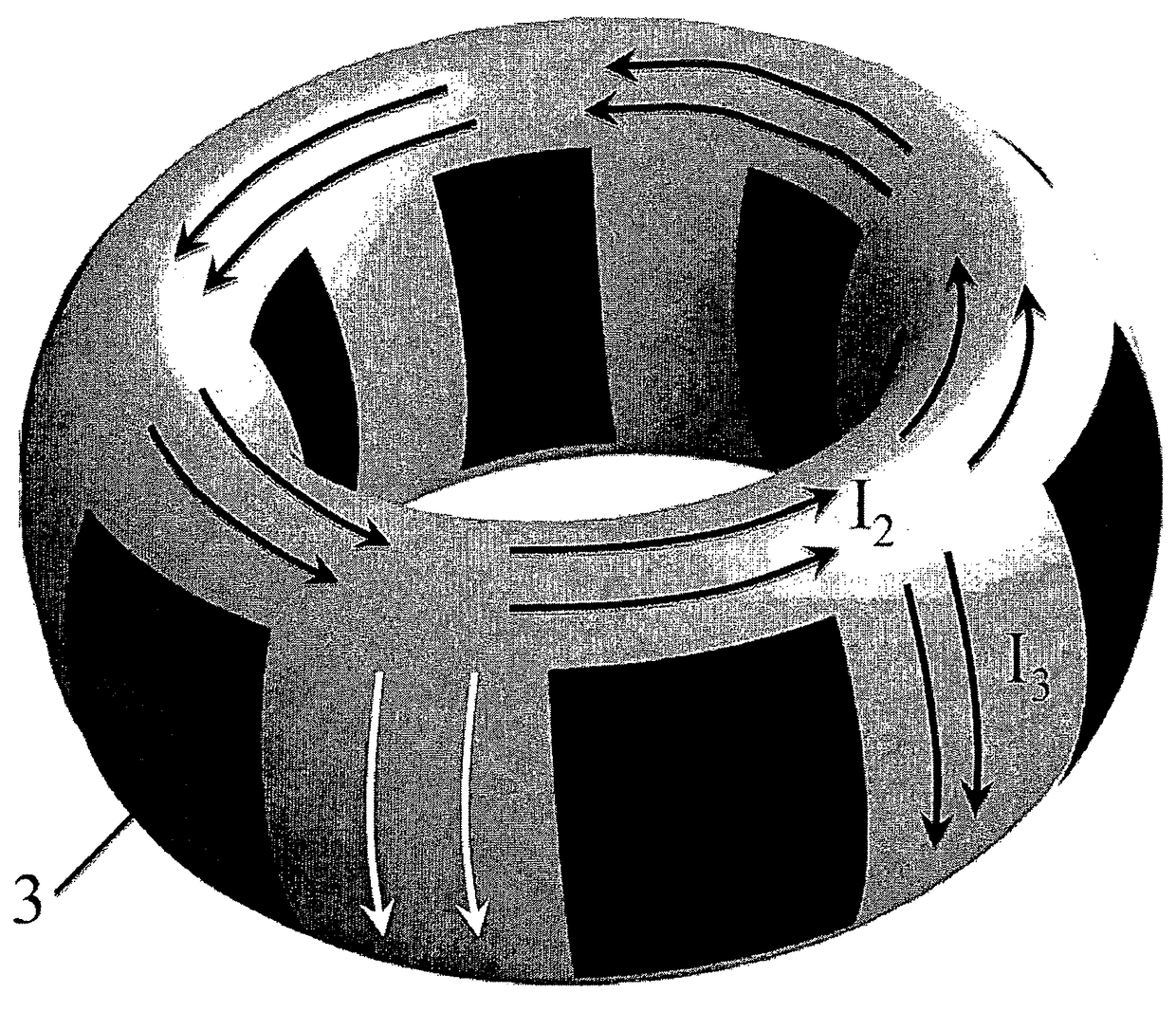
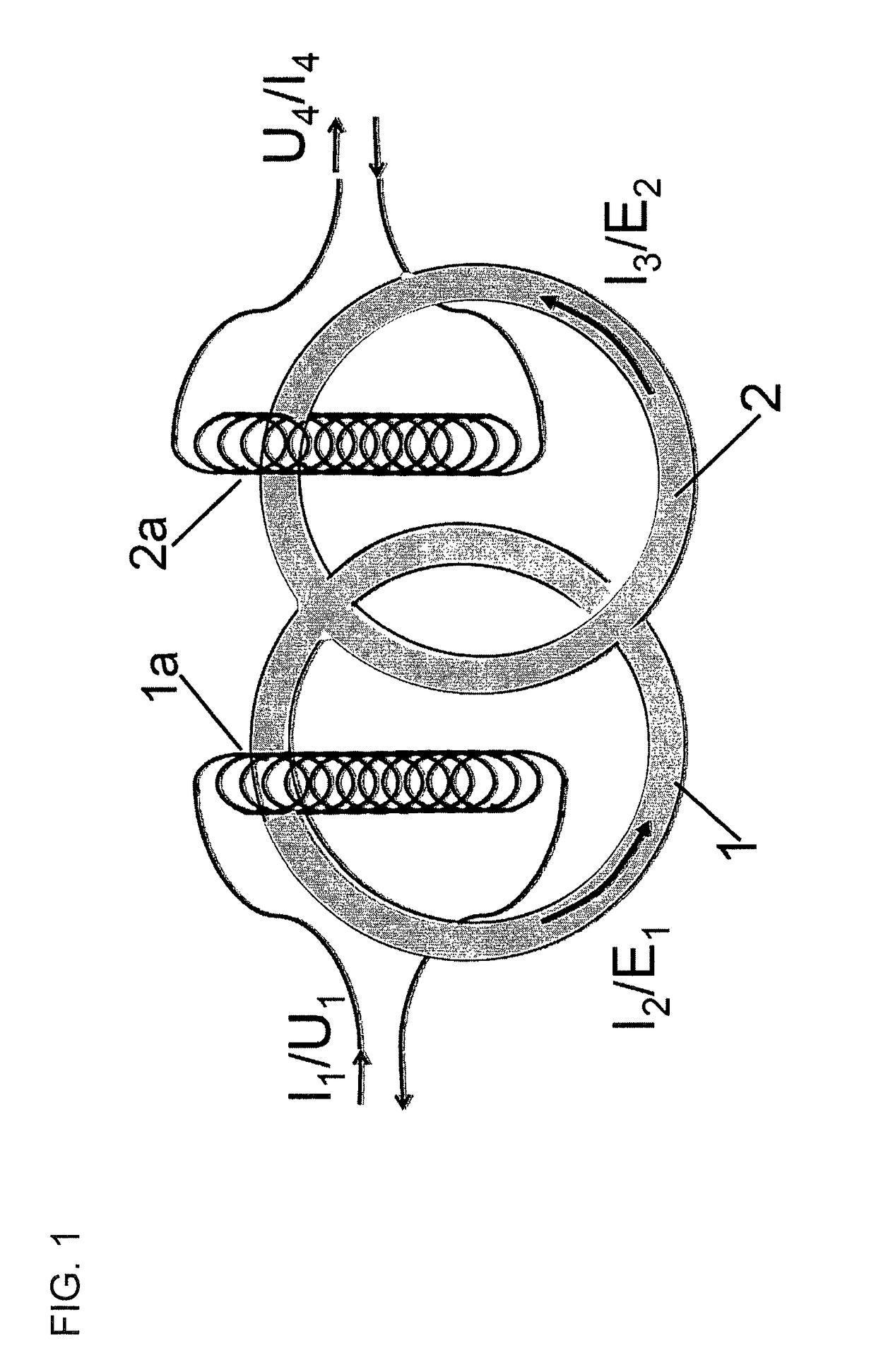
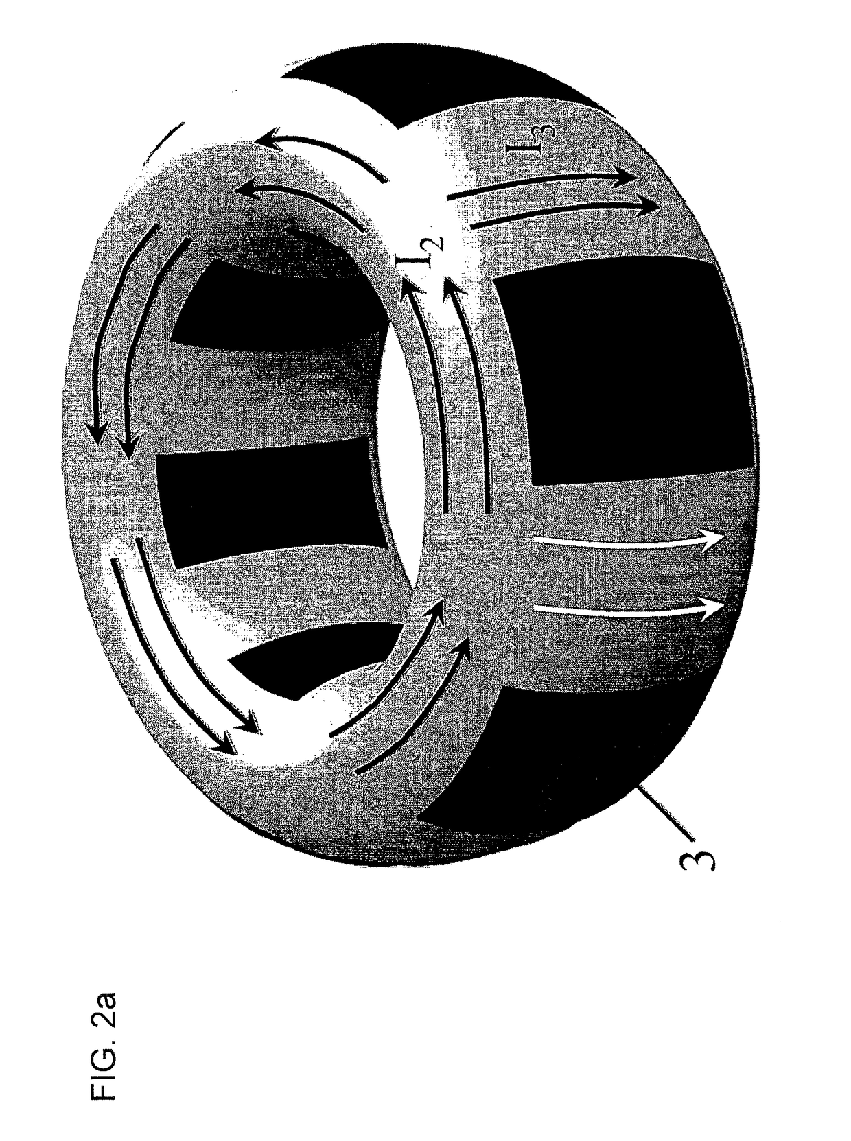
[0032]FIG. 1 shows a schematic illustration of an exemplary embodiment of the gyrator according to the invention. The Hall effect material is segmented into two conductor loops 1 and 2. The magnetic field, which is not shown for the sake of clarity, is homogenous in this space and located perpendicularly to the drawing plane. Coils 1a and 2a are wound around the conductor loops 1 and 2, respectively. An input current I1, which is coupled in via the coil 1a, produces an electromotive force E1 in conductor loop 1. The Hall effect converts this electromotive force into a current I3 through conductor loop 2. This current induces the output voltage U4 in the coil 2a. If, conversely, an input current I4 flows through the coil 2a, this produces an electromotive force E2 in conductor loop 2. As a result of the right-hand rule, the Hall effect converts this electromotive force E2 into a current I2 through conductor loop 1 which is 180° phase-shifted in relation to the input current, at the s...


PUM


Abstract

A gyrator for AC signals comprises a Hall effect material, means for coupling an alternating current (I1; I4) into the Hall effect material, means for permeating a Hall effect material with a magnetic field that is perpendicular to the plane or surface of the material, and means far converting a current (I3; I2), which was generated by the current I1 perpendicularly to the electric field generated by I1 in the Hall effect material, into an output voltage (U4; U1). A transformer is provided between at least one conductor loop (1a; 2a) made of a normal-conducting or semi-conducting material and at least one conductor loop (1; 2) made of the Hall effect material for coupling the current (I1; I4) into the Hall effect material and / or for converting the current (I3; I2) in the Hall effect material into the output voltage (U4; U1). It was found that eliminating an inefficient galvanic coupling of the Hall effect material to metallic or semi-conducting conductors minimizes the dissipative losses that occur during the conversion of the input current (I1; I4) into the output voltage (U4; U1). The gyrator can thus also be used for highly sensitive experiments in quantum information processing at low temperatures.

Description

[0001]The invention relates to a gyrator for AC signalsBACKGROUND OF THE INVENTION[0002]A gyrator is an electric two-port network element in which the voltage at the output is proportional to the current at the input, the sign of the voltage changing when the input and output are reversed, if the current is an alternating current, the same is thus converted into either an in-phase alternating voltage or an alternating voltage in phase opposition, depending on the port of the gyrator to which this current is applied. The gyrator is necessary as a fifth linear element, in addition to the resistor, capacitor, inductor and ideal transformer, to realize two-port network elements that allow an alternating voltage to pass only in one direction (isolators), or three-port or multi-port elements that allow an alternating voltage to pass a port only to a next port in a fixed rotational direction (circulators).[0003]So as to render the conversion of the input current into the output voltage dep...

Claims


Application Information

Patent Timeline
IPC IPC(8): H01L43/06H03H7/00
CPCH03H7/002H01L43/06H10N52/00
Inventor DIVINCENZO, DAVID
Owner FORSCHUNGSZENTRUM JULICH GMBH
Why Eureka
Try Eureka