High-efficiency broadband antenna

a broadband antenna and high-efficiency technology, applied in the direction of resonant antennas, elongated active element feeds, differential interacting antenna combinations, etc., can solve the problems of prior art design efficiency, based on real-world testing, not living up to initial expectations

Active Publication Date: 2017-05-09
WORLDWIDE ANTENNA SYST LLC
View PDF12 Cites 0 Cited by
  • Summary
  • Abstract
  • Description
  • Claims
  • Application Information

AI Technical Summary

Benefits of technology

[0006]Described herein are embodiments including a high-efficiency broadband antenna comprising: a D-plate comprising a horizontal conductor raised above and insulated from a ground plane, and a D-plate feed conductor; an E-cylinder comprising a vertical hollow conductive cylinder of smaller diameter than the D-plate, which is mounted concentrically above and insulated from the D-plate, and an E-cylinder feed

Problems solved by technology

Although there was initial excitement about such antennas in the 1980s and early 1990s, the efficie

Method used


Image

  • High-efficiency broadband antenna
  • High-efficiency broadband antenna
  • High-efficiency broadband antenna

Examples


Embodiment Construction

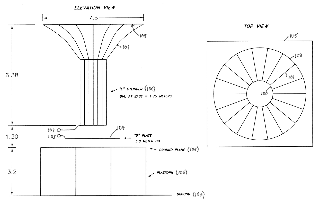
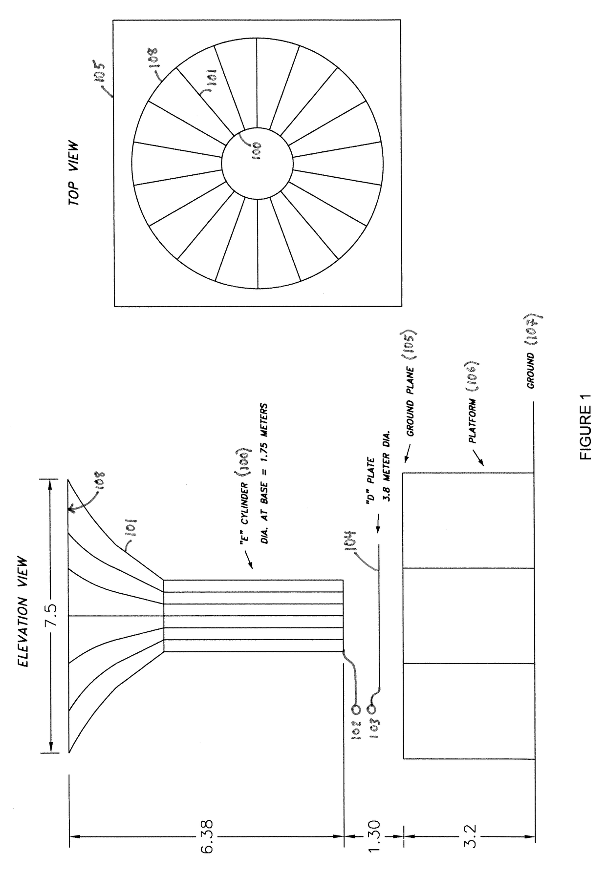
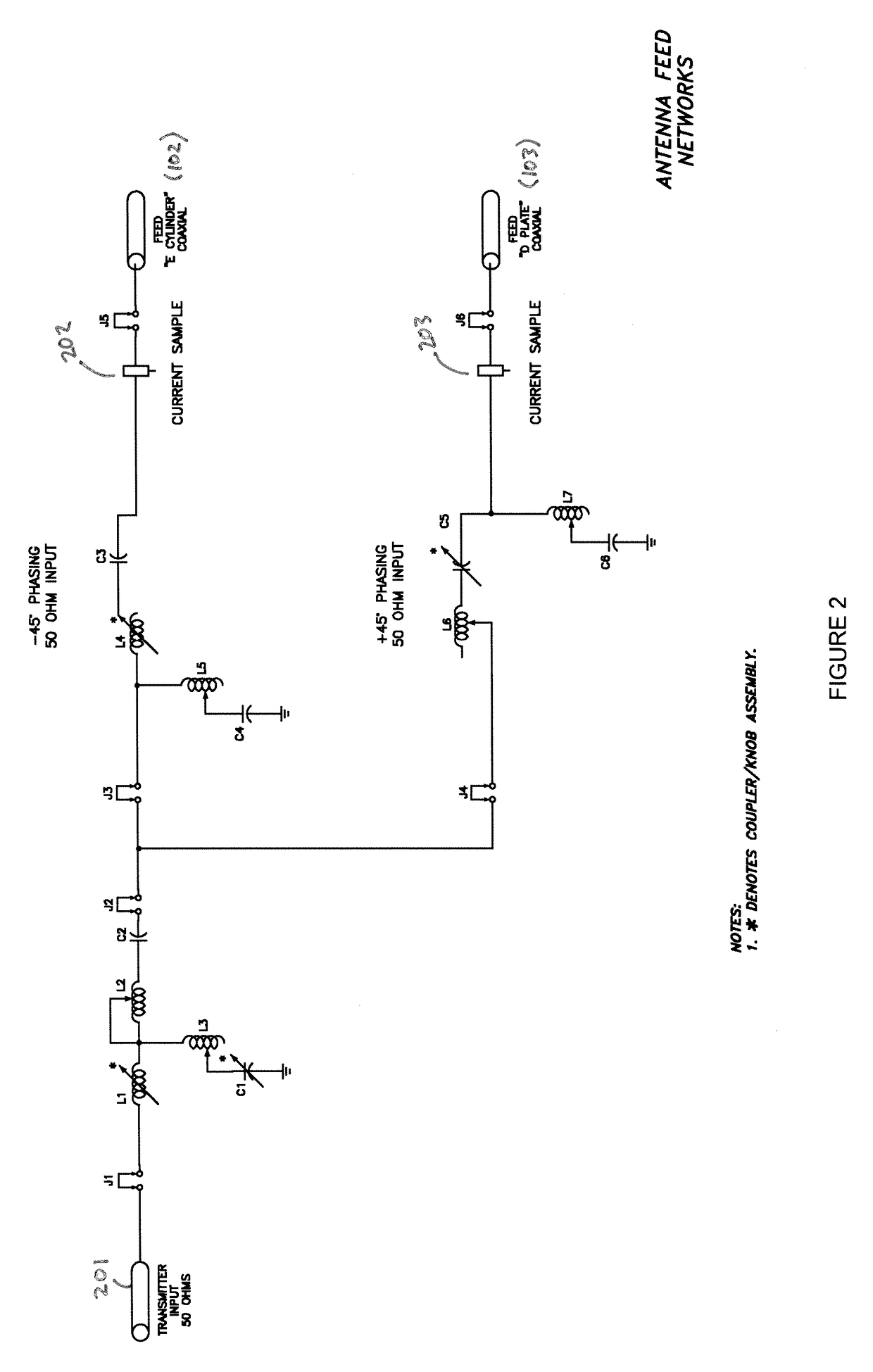
[0015]The present disclosure describes high-efficiency broadband antennas and associated circuitry systems that overcome the efficiency limitations of prior art CFAs.

[0016]Various example embodiments of the present inventions are described herein. Those of ordinary skill in the art will realize that the following detailed description is illustrative only and is not intended to be in any way limiting. Other embodiments will readily suggest themselves to such skilled persons having the benefit of this disclosure.

[0017]In the interest of clarity, not all of the routine features of the implementations described herein are shown and described. In the development of any such actual implementation, numerous implementation-specific decisions must be made in order to achieve the developer's specific goals, such as compliance with application, safety, regulatory, and business constraints, and that these specific goals will vary from one implementation to another and from one developer to anot...


PUM


Abstract

A design for high-efficiency broadband antennas which includes a D-plate and an E-cylinder, electrically insulated from each other, the E-cylinder being above the D-plate, and both parts insulated from a ground plane. The E-cylinder and D-plate may be fed by distinct feed networks with adjustable impedance.

Description

CROSS-REFERENCE TO RELATED APPLICATION[0001]This application claims priority to U.S. Provisional Application No. 61 / 800,184, entitled “High-Efficiency Broadband Antenna,” filed 15 Mar. 2013, the entire disclosure of which is hereby incorporated by reference.TECHNICAL FIELD[0002]This application relates to crossed-field radio-frequency antennas.BACKGROUND[0003]A crossed-field antenna (“CFA”) is a type of antenna designed for long and medium wave broadcasting. Conventional CFAs were first developed by Hately & Kabbary (see U.S. Pat. No. 5,155,495, issued 13 Oct. 1992; U.S. Pat. No. 6,025,813, issued 15 Feb. 2000; and U.S. Pat. No. 7,113,138, issued 26 Sep. 2006). These authors describe an antenna with two parts, one of which produces a high frequency electric field, and the other of which produces a high frequency magnetic field. The electric and magnetic field lines are arranged to cross, and thereby synthesize and propagate radio waves. CFAs based on the Hately and Kabbary design ty...

Claims


Application Information

Patent Timeline
IPC IPC(8): H01Q9/00H01Q1/36H01Q1/50
CPCH01Q1/36H01Q1/50H01Q9/40H01Q21/29H03H7/21
Inventor GORMAN, KURT
Owner WORLDWIDE ANTENNA SYST LLC
Why Eureka
Try Eureka