
Emissions reduction for CO2 capture

a carbon dioxide and capture process technology, applied in the direction of separation processes, dispersed particle separation, chemistry apparatuses and processes, etc., can solve problems such as producing other unwanted emissions, and achieve the effect of reducing the unwanted compounds produced by the carbon capture process

Inactive Publication Date: 2017-05-09
FLUOR TECH CORP
View PDF31 Cites 3 Cited by
  • Summary
  • Abstract
  • Description
  • Claims
  • Application Information

AI Technical Summary

Benefits of technology

This patent is about systems for reducing emissions during carbon capture. The system includes a plasma generator that injects radical species into the carbon capture absorber. This plasma generator is external to the absorber and uses atmospheric air. The plasma generator is located close to the absorber to maximize the lifetime of the radical species inside the absorber. The technical effect of this patent is to improve the efficiency and effectiveness of carbon capture processes.

Problems solved by technology

Unfortunately, some CO2 capture technologies produce other unwanted emissions, such as, monoethanolamine (MEA), diethanolamine (DEA), methyldiethanolamine (MDEA), piperazine, diglycolamine (DGA), 2-Amino-2-methyl-1-propanol (2-AMP), methylamines, formaldehyde, acetaldehyde, methanol, ammonia, nitrosamines, and amine degradation products.

Method used


Image

  • Emissions reduction for CO<sub>2 </sub>capture
  • Emissions reduction for CO<sub>2 </sub>capture
  • Emissions reduction for CO<sub>2 </sub>capture

Examples


Embodiment Construction

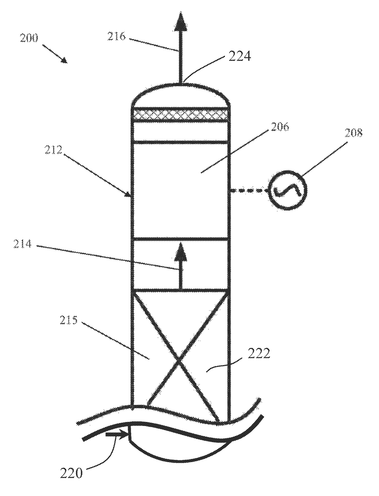
[0019]One should appreciate that the disclosed techniques provide many advantageous technical effects including methods and devices for reducing harmful and / or unwanted emissions from carbon capture processes.

[0020]The following discussion provides many example embodiments of the inventive subject matter. Although each embodiment represents a single combination of inventive elements, the inventive subject matter is considered to include all possible combinations of the disclosed elements. Thus if one embodiment comprises elements A, B, and C, and a second embodiment comprises elements B and D, then the inventive subject matter is also considered to include other remaining combinations of A, B, C, or D, even if not explicitly disclosed.

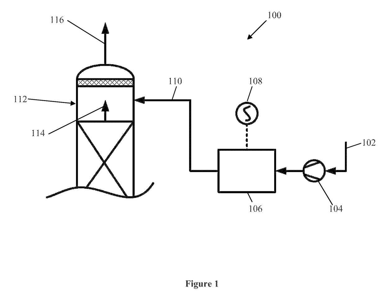
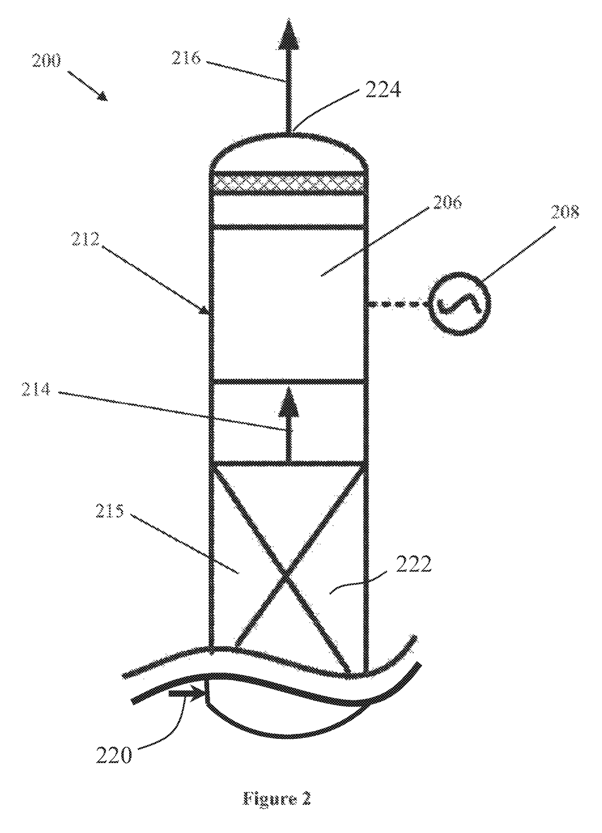
[0021]FIG. 1 shows a system 100 for reducing carbon capture emissions. Atmospheric air 102 is drawn into blower 104 and pushed into non-thermal plasma (NIP) generator 106. Power source 108 produces an electrical field within NTP generator 106. As atmos...


PUM


Abstract

Systems and processes for reducing carbon capture emissions are described. The process involves introducing a radical species into a decarbonized combustion gas. The radical species react with residual amines or unwanted compounds in the decarbonized combustion gas, thus reducing the concentration of residual amines or unwanted compounds in the exhaust gas. The system includes a carbon capture absorber with non-thermal plasma generator configured to provide radical species reducing the concentration of residual amines or unwanted compounds in the exhaust combustion gas.

Description

[0001]This application claims priority to U.S. Provisional Patent Application Ser. No. 61 / 615,428 filed on Mar. 26, 2012. This and all other referenced extrinsic materials are incorporated herein by reference in their entirety. Where a definition or use of a term in a reference that is incorporated by reference is inconsistent or contrary to the definition of that term provided herein, the definition of that term provided herein is deemed to be controlling.FIELD OF THE INVENTION[0002]The field of the invention is emissions reduction for carbon dioxide (CO2) capture processes.BACKGROUND[0003]The following description includes information that may be useful in understanding the present invention. It is not an admission that any of the information provided herein is prior art or relevant to the presently claimed invention, or that any publication specifically or implicitly referenced is prior art.[0004]Carbon dioxide (CO2) capture processes and technologies are commonly used in fossil ...

Claims


Application Information

Patent Timeline
Patent Type & Authority Patents(United States)
IPC IPC(8): B01D53/62B01D53/32B01D53/54B01D53/58B01D53/72B01D53/79B01D53/14
CPCB01D53/79B01D53/1475B01D53/32B01D53/323B01D53/54B01D53/58B01D53/62B01D53/72B01D2252/102B01D2252/204B01D2252/2021B01D2252/20405B01D2252/20447B01D2252/20484B01D2252/20489B01D2257/504B01D2258/0283B01D2259/818Y02C10/04Y02C10/06Y02A50/20Y02C20/40
Inventor REDDY, SATISHYONKOSKI, JOSEPH
Owner FLUOR TECH CORP
Learn More