
Apparatus and method for deactivating power-saving mode, relay device, and computer-readable storage medium for computer program

a technology of power-saving mode and relay device, which is applied in the direction of digital output to print unit, high-level techniques, instruments, etc., can solve the problem that the power-saving mode of some image forming apparatuses cannot be deactivated appropriately

Active Publication Date: 2017-05-02
KONICA MINOLTA BUSINESS TECH INC
View PDF22 Cites 4 Cited by
  • Summary
  • Abstract
  • Description
  • Claims
  • Application Information

AI Technical Summary

Benefits of technology

The patent aims to improve power-saving in a network where different types of image forming apparatuses are provided. The technical effect is to deactivate the power-saving mode of an image forming apparatus more reliably than conventionally possible.

Problems solved by technology

According to the conventional methods, in a network in which different types of image forming apparatuses are provided, power-saving modes of some of the image forming apparatuses cannot be deactivated appropriately.

Method used


Image

  • Apparatus and method for deactivating power-saving mode, relay device, and computer-readable storage medium for computer program
  • Apparatus and method for deactivating power-saving mode, relay device, and computer-readable storage medium for computer program
  • Apparatus and method for deactivating power-saving mode, relay device, and computer-readable storage medium for computer program

Examples


Embodiment Construction

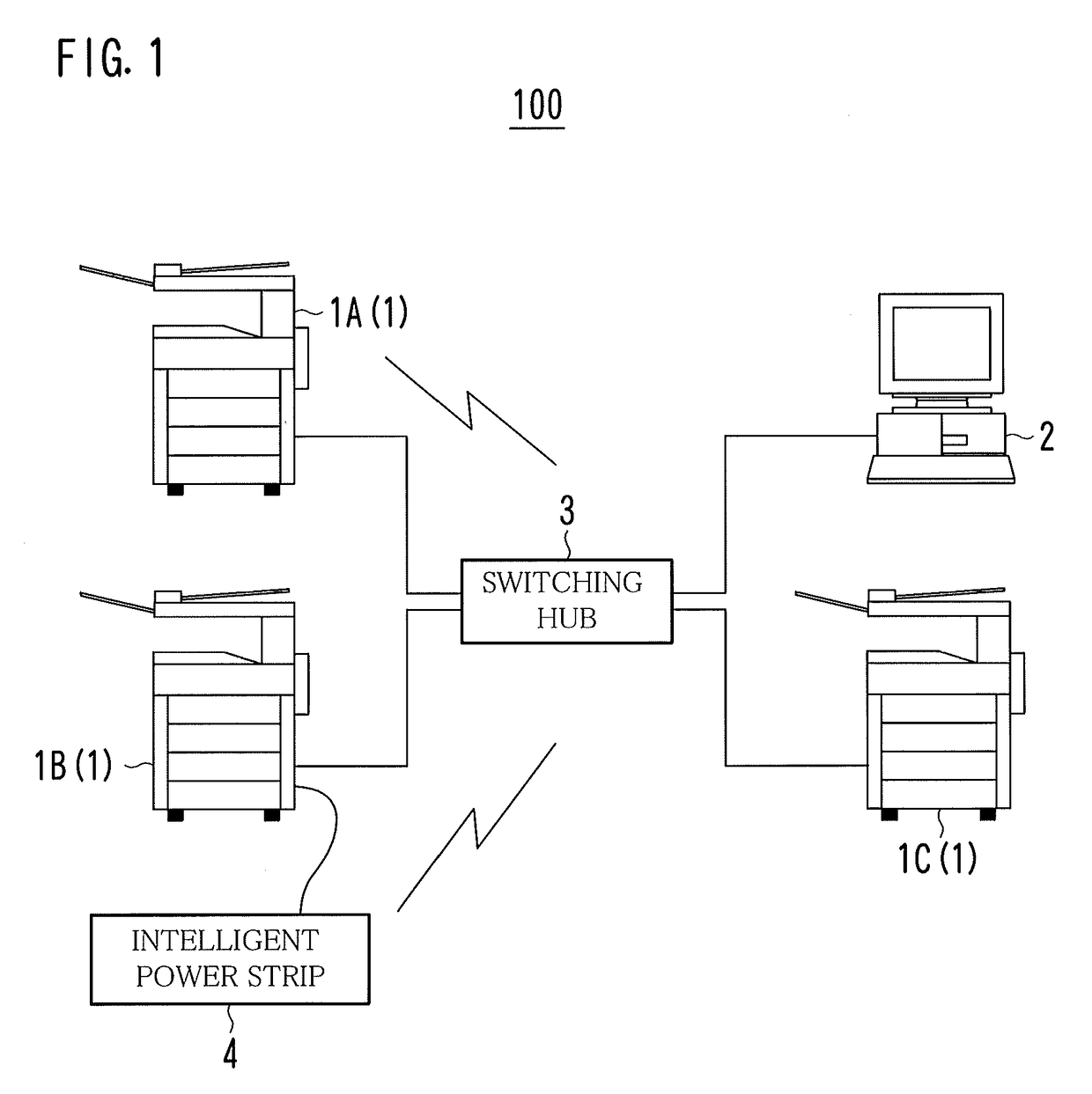
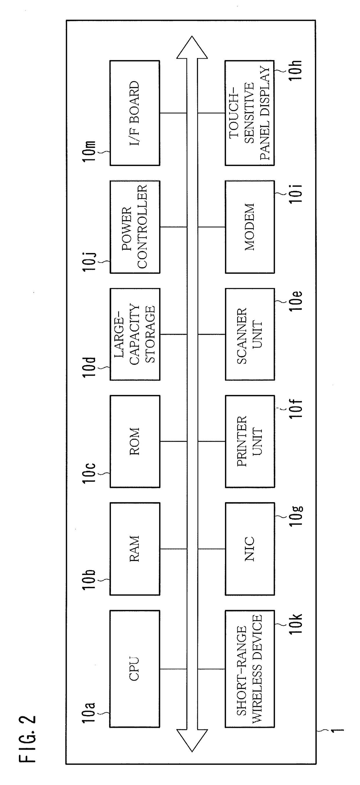
[0039]FIG. 1 is a diagram showing an example of the overall configuration of a printing system 100; FIG. 2 is a diagram showing an example of the hardware configuration of an image forming apparatus 1; FIG. 3 is a diagram showing an example of the hardware configuration of a switching hub 3; FIG. 4 is a diagram showing an example of the functional configuration of the switching hub 3; FIG. 5 is a diagram showing an example of differences between image forming apparatuses 1A-1C in specifications; FIGS. 6A and 6B are diagrams showing an example as to how the image forming apparatus 1A is supplied with power; FIG. 7 is a diagram showing an example of a platform of an intelligent power strip 4; and FIGS. 8A and 8B are diagrams showing an example as to how the image forming apparatus 1B is supplied with power.

[0040]Referring to FIG. 1, the printing system 100 is configured of a plurality of image forming apparatuses 1, at least one terminal 2, the switching hub 3, the intelligent power s...


PUM


Abstract

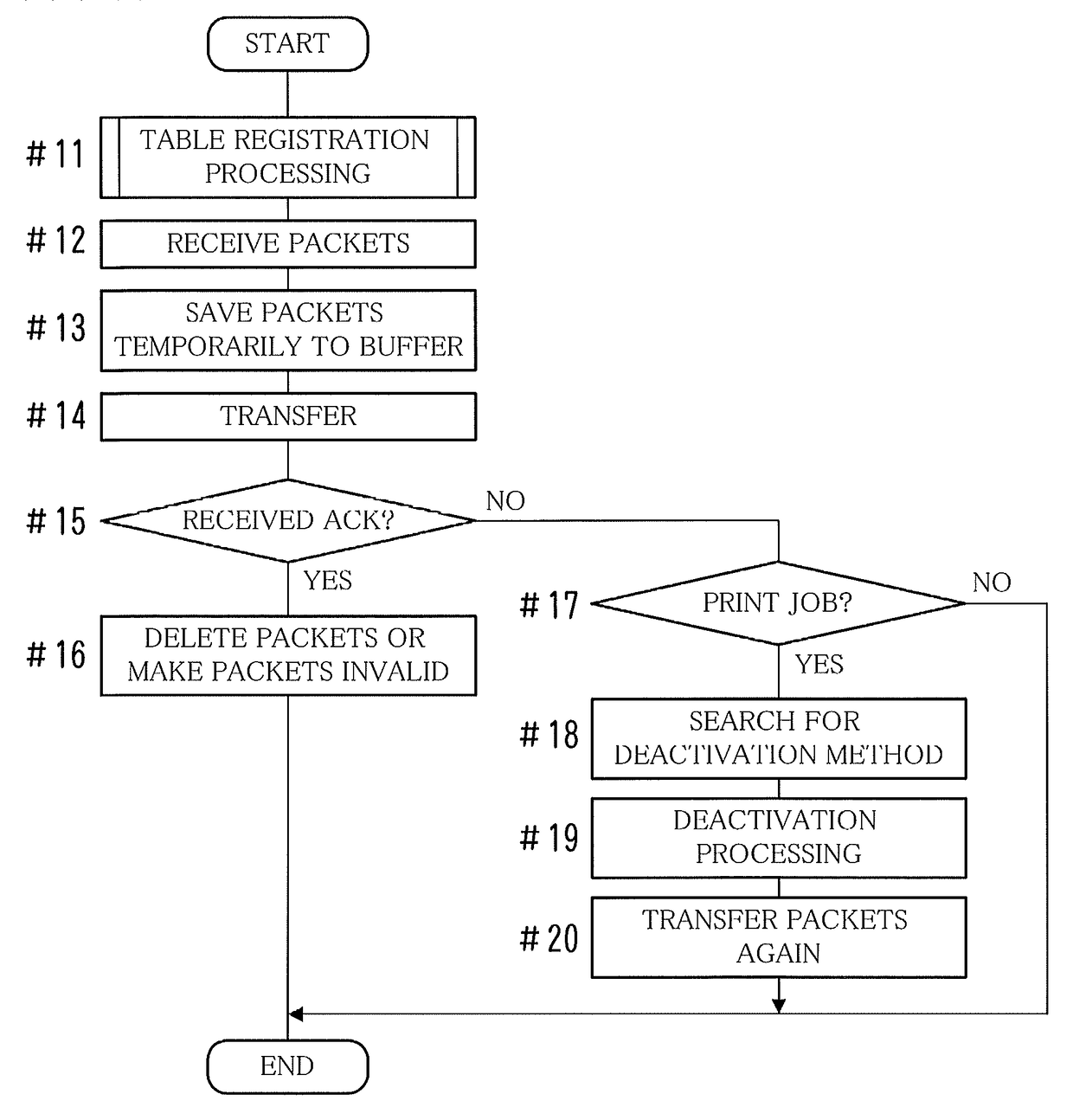
A power-saving mode deactivation apparatus for performing communication via a communication network with specific processing apparatuses for particular processing is provided. The power-saving mode deactivation apparatus includes a storage portion for storing therein a deactivation method for deactivating a power-saving mode of each of the specific processing apparatuses; a detection portion for detecting that particular processing data for the particular processing is not delivered to, among the specific processing apparatuses, a destination specific processing apparatus of the particular processing data, and a deactivation portion for performing, when the detection portion detects that the particular processing data is not delivered to the destination specific processing apparatus, deactivation processing for deactivating a power-saving mode of the destination specific processing apparatus based on the deactivation method, stored in the storage portion, for the destination specific processing apparatus.

Description

[0001]This application is based on Japanese patent application No. 2011-191936 filed on Sep. 2, 2011, the contents of which are hereby incorporated by reference.BACKGROUND OF THE INVENTION[0002]1. Field of the Invention[0003]The present invention relates to a technology for deactivating a power-saving mode of a specific processing apparatus performing particular processing, e.g., an image forming apparatus.[0004]2. Description of the Related Art[0005]In recent years, many different methods have been proposed for reducing power requirements of a variety of products. A method for reducing power requirements of an image forming apparatus is also proposed.[0006]According to a conventional method, by shifting a power state in a printer that is supplied with power through a power control device from a normal power state to a power-saving state by connecting a power cord to an outlet of the power control device, the supply of the power from the outlet of the power control device to the pri...

Claims


Application Information

Patent Timeline
Patent Type & Authority Patents(United States)
IPC IPC(8): G06F15/00H04L12/12H04N1/00H04N1/32
CPCH04N1/00891H04L12/12H04N1/00896H04N1/00907H04N1/32502H04N2201/0094Y02B60/32Y02B60/34Y02D30/50
Inventor OHSHIMA, ATSUSHITERAMOTO, KEISUKEYAMADA, MASAMISHIBUTA, YOSHIAKIKUBO, HIROAKI
Owner KONICA MINOLTA BUSINESS TECH INC
Learn More