
Outdoor dry-type transformer

a transformer and dry-type technology, applied in the direction of transformer/inductance details, transformer/inductance corrosion protection, electrical equipment, etc., can solve the problems of increasing the size and cost of the transformer

Active Publication Date: 2017-05-02
HITACHI ENERGY LTD
View PDF58 Cites 7 Cited by
  • Summary
  • Abstract
  • Description
  • Claims
  • Application Information

AI Technical Summary

Problems solved by technology

The housing for a conventional outdoor transformer increases the size and cost of the transformer.
In addition, for liquid-filled transformers, anomalous events, such as lightning strikes and traffic accidents, can result in the tank being compromised and the dielectric fluid spilling into the surrounding area, which can present environmental issues.

Method used


Image

  • Outdoor dry-type transformer
  • Outdoor dry-type transformer
  • Outdoor dry-type transformer

Examples


Embodiment Construction

[0013]It should be noted that in the detailed description that follows, identical components have the same reference numerals, regardless of whether they are shown in different embodiments of the present invention. It should also be noted that in order to clearly and concisely disclose the present invention, the drawings may not necessarily be to scale and certain features of the invention may be shown in somewhat schematic form.

[0014]The present invention is directed to a dry-type, distribution transformer adapted for outdoor mounting without the need to be enclosed inside a protective housing. The transformer may be single phase or three phase and may be mounted to a utility pole or to a pad on the ground.

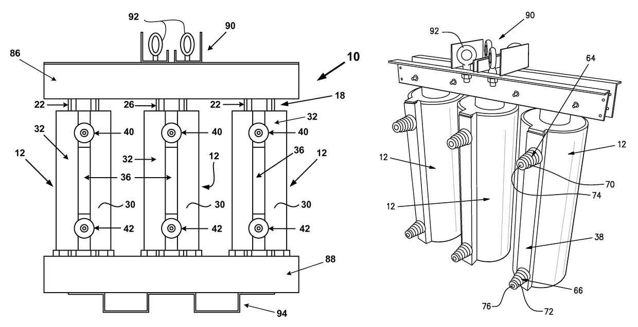
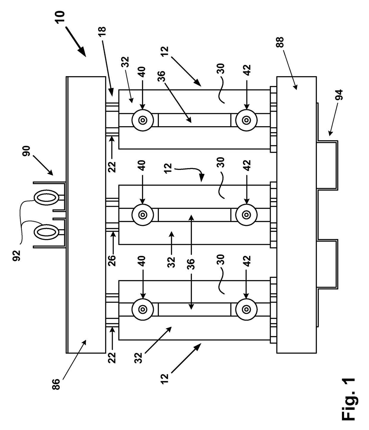
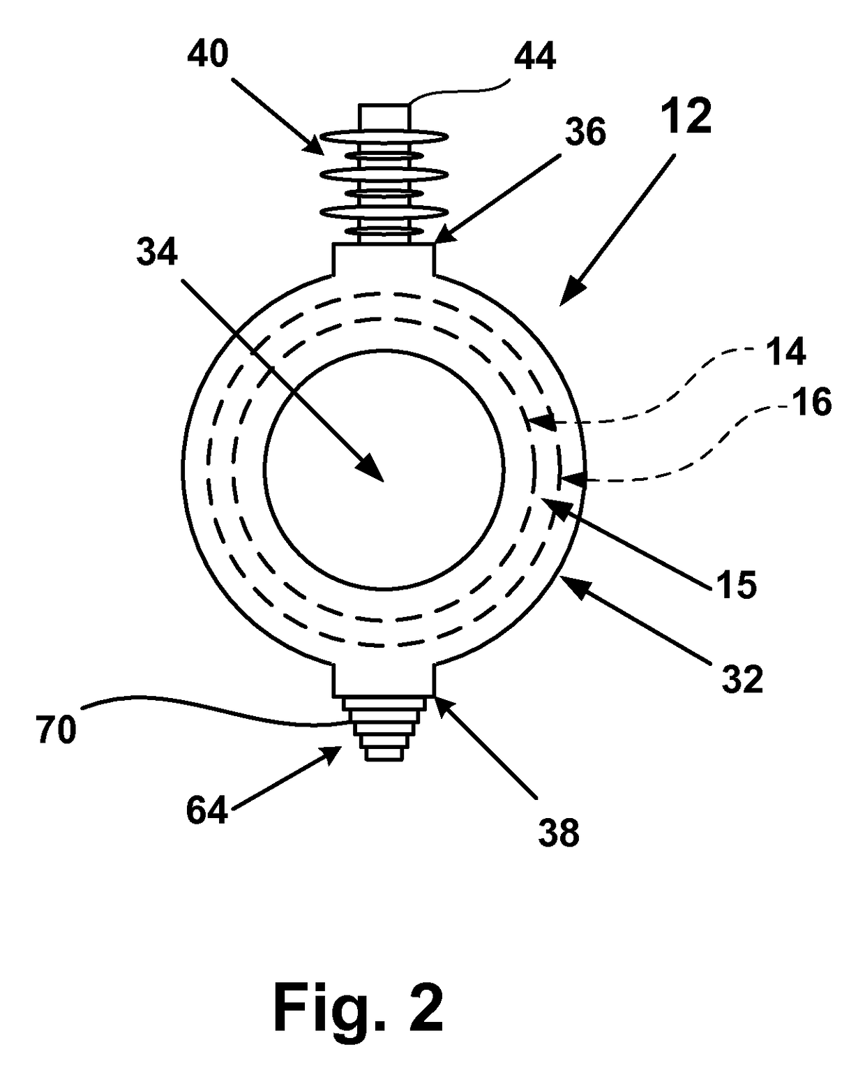
[0015]Referring now to FIGS. 1 and 2, a three-phase transformer 10 constructed in accordance with the present invention is shown. The transformer 10 comprises three winding assemblies 12 (one for each phase) mounted to a core 18. The core 18 is comprised of ferromagnetic metal an...


PUM

PropertyMeasurementUnit
voltageaaaaaaaaaa
voltageaaaaaaaaaa
output voltageaaaaaaaaaa

Abstract

A three-phase dry distribution transformer adapted for mounting outdoors on a pad or to a utility pole. The distribution transformer includes one or more winding assemblies mounted to a ferromagnetic core. Each winding assembly includes a low voltage winding and a high voltage winding. In each winding assembly, an encasement comprised of an insulating resin encapsulates the low voltage and high voltage windings. The encasement includes a body and a pair of high voltage bushings and a pair of low voltage bushing.

Description

CROSS-REFERENCE TO RELATED APPLICATION[0001]This application claims the benefit of U.S. provisional patent application No. 61 / 321,852 filed on Apr. 7, 2010, which is hereby incorporated by reference in its entirety.BACKGROUND OF THE INVENTION[0002]The present invention relates to transformers and more particularly to distribution transformers for outdoor mounting.[0003]Power is often provided from utilities to residences and small businesses through distribution transformers disposed outdoors (not in a building). Such outdoor transformers may be mounted on a pad or on a utility pole. Conventionally, such outdoor distribution transformers include a core and coil assembly disposed inside a housing. If the transformer is liquid-filled, the housing may enclose or include a tank filled with a dielectric fluid for cooling the core and coil assembly. If the transformer is a dry transformer, the housing may be a ventilated structure that permits air to flow in and out, while providing prote...

Claims


Application Information

Patent Timeline
Patent Type & Authority Patents(United States)
IPC IPC(8): H01F30/12H01F27/02H01F27/32H01F27/23
CPCH01F27/23H01F27/327H01F30/12H01F2027/328
Inventor SINGH, BANDEEPHARTMANN, THOMASPAULEY, JR., WILLIAM E.
Owner HITACHI ENERGY LTD
Learn More