Radio communication system, radio base station, and base station parameter-adjustment method
a radio communication system and parameter adjustment technology, applied in the field of radio communication systems, radio base stations, and base station parameter adjustment methods, can solve problems such as increasing and achieve the effect of reducing unfairness among radio terminals
- Summary
- Abstract
- Description
- Claims
- Application Information
AI Technical Summary
Benefits of technology
Problems solved by technology
Method used
Image

Examples
first embodiment
[0028](1) First Embodiment
[0029]In the first embodiment, (1.1) configuration of radio communication system, (1.2) configuration of radio base station, (1.3) operation of radio communication system, and (1.4) effects and advantages are described in this order.
[0030](1.1) Configuration of Radio Communication System
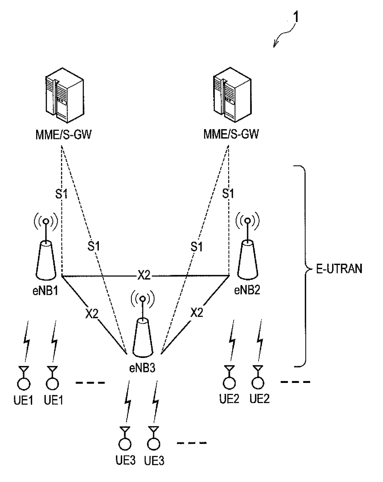
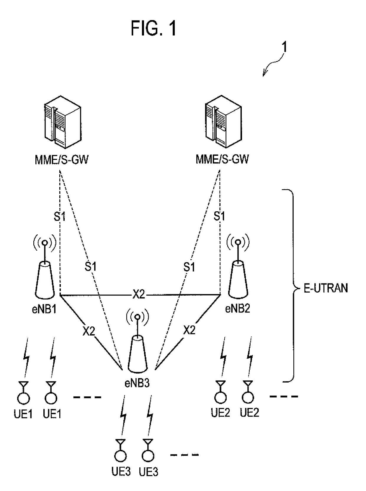
[0031]FIG. 1 is a view showing a configuration of a radio communication system 1 of the first embodiment. The radio communication system 1 is configured according to LTE standards.
[0032]As shown in FIG. 1, multiple radio base stations eNB (radio base stations eNB1 to eNB3) form an E-UTRAN (Evolved-UMTS Terrestrial Radio Access Network). Each of the multiple radio base stations eNB forms a cell which is a communication area for providing a service to radio terminals UE.
[0033]Adjacent radio base stations eNB can communicate via an X2 interface being a logical communication path providing inter-base station communication. Each of the multiple radio base stations eNB can communi...
second embodiment
[0080](2) Second Embodiment
[0081]Hereafter, a description is given of a second embodiment of the present invention mainly on points different from the first embodiment. While the radio base station eNB1 being the load-information reception side performs correction in the first embodiment, the radio base station eNB2 being the load-information transmission side performs correction instead of the radio base station eNB1 in the second embodiment.
[0082](2.1) Configuration of Radio Base Station eNB2
[0083]Next, a description is given of a configuration of the radio base station eNB2 of the second embodiment. FIG. 4 is a block diagram showing a configuration of the radio base station eNB2.
[0084]As shown in FIG. 4, the radio base station eNB2 includes an antenna unit 201, a radio communication unit 210, a controller 220, a storage 230, and a network communication unit 240.
[0085]The antenna unit 201 is used to send and receive radio signals. The radio communication unit 210 is formed of a ra...
third embodiment
[0115](3) Third Embodiment
[0116]Hereafter, a description is given of a third embodiment of the present invention mainly on points different from the first and second embodiments. In the first embodiment, the radio base station eNB1 being the load-information reception side performs correction, and in the second embodiment, the radio base station eNB2 being the load-information transmission side performs correction instead of the radio base station eNB1. In the third embodiment, a description is given of a case where correction is performed by both of the radio base station eNB1 and the radio base station eNB2.
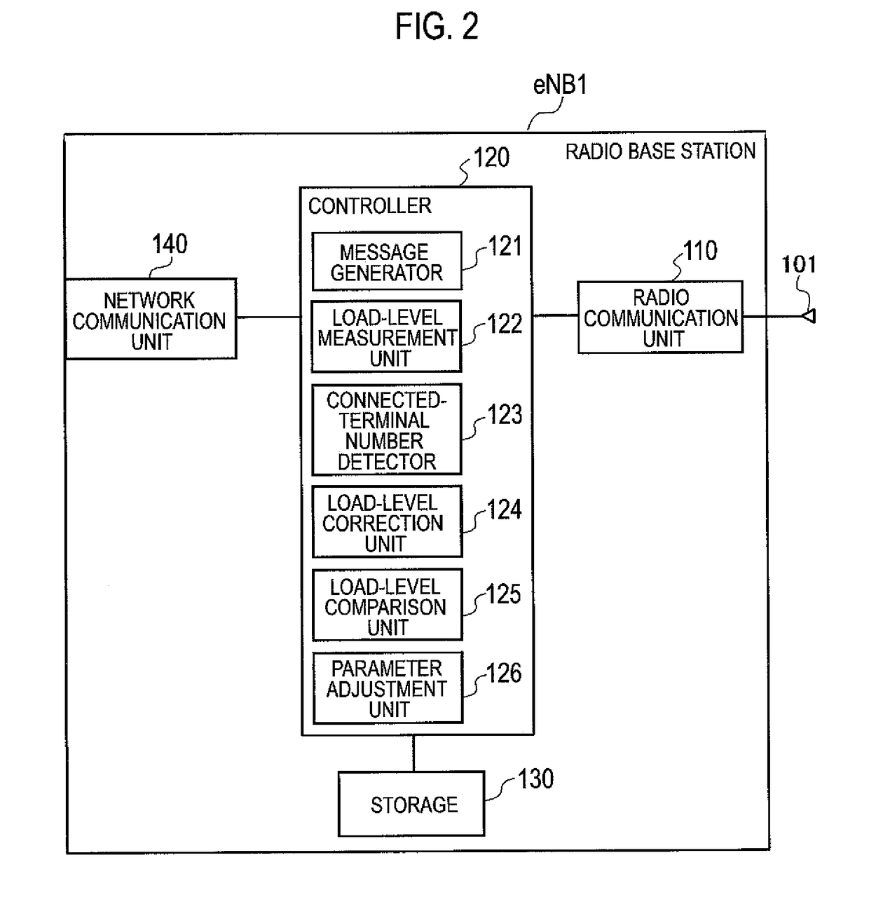
[0117]FIG. 6 is an operation sequence chart showing an operation of the radio communication system 1 of the third embodiment. The configuration of FIG. 2 is referred to as the configuration of the radio base station eNB1, and the configuration of FIG. 4 is referred to as the configuration of the radio base station eNB2.
[0118]Processing of steps S301 to S306 is the same as that ...
PUM
 Abstract
Description
Claims
Application Information
 - Generate Ideas
- Intellectual Property
- Life Sciences
- Materials
- Tech Scout
- Unparalleled Data Quality
- Higher Quality Content
- 60% Fewer Hallucinations
Browse by: Latest US Patents, China's latest patents, Technical Efficacy Thesaurus, Application Domain, Technology Topic, Popular Technical Reports.
© 2025 PatSnap. All rights reserved.Legal|Privacy policy|Modern Slavery Act Transparency Statement|Sitemap|About US| Contact US: help@patsnap.com