Display panels

a technology of display panels and panels, applied in non-linear optics, instruments, optics, etc., can solve the problems of poor elastic recovery of cone-shaped or column-shaped photo spacers, great number of photo spacers used in the lcd panel. , to achieve the effect of reducing the aperture ratio of the lcd panel, poor elastic recovery, and great number of photo spacers

Active Publication Date: 2017-04-25
INNOLUX CORP
View PDF6 Cites 0 Cited by
  • Summary
  • Abstract
  • Description
  • Claims
  • Application Information

AI Technical Summary

Benefits of technology

[0008]Photo spacers usually have the shape of a cone or a column to support the gap between the CF substrate and the TFT substrate. However, the cone-shaped or the column-shaped photo spacers have a poor elastic recovery. Thus, the number of photo spacers used in LCD panels is great. An increase in the number of photo spacers used in LCD panels will reduce the aperture ratio of the LCD panels, which is disadvantageous to the LCD panels with high resolution.
[0009]Accordingly, the disclosure provides an improvement in the structure of spacers used in display panels. The spacer has an undercut structure that is a shrinking structural design at a location near the bottom of the spacer. The undercut structure can increase the elastic recovery of the spacer. Therefore, when the spacers of the embodiments of the disclosure are applied to LCD panels of high resolution, the number of spacers used in the LCD panels is decreased and the aperture ratio of the LCD panels is thereby increased. Moreover, the disclosure provides thickness designs of an alignment film that covers the spacer. The thickness designs of the alignment film can enhance the adhesion between the spacer and the substrate of the LCD panels. Furthermore, the thickness designs of the alignment film are advantageous to the alignment of liquid-crystal molecules in the LCD panels.

Problems solved by technology

However, the cone-shaped or the column-shaped photo spacers have a poor elastic recovery.
Thus, the number of photo spacers used in LCD panels is great.
An increase in the number of photo spacers used in LCD panels will reduce the aperture ratio of the LCD panels, which is disadvantageous to the LCD panels with high resolution.

Method used


Image

  • Display panels
  • Display panels
  • Display panels

Examples


Embodiment Construction

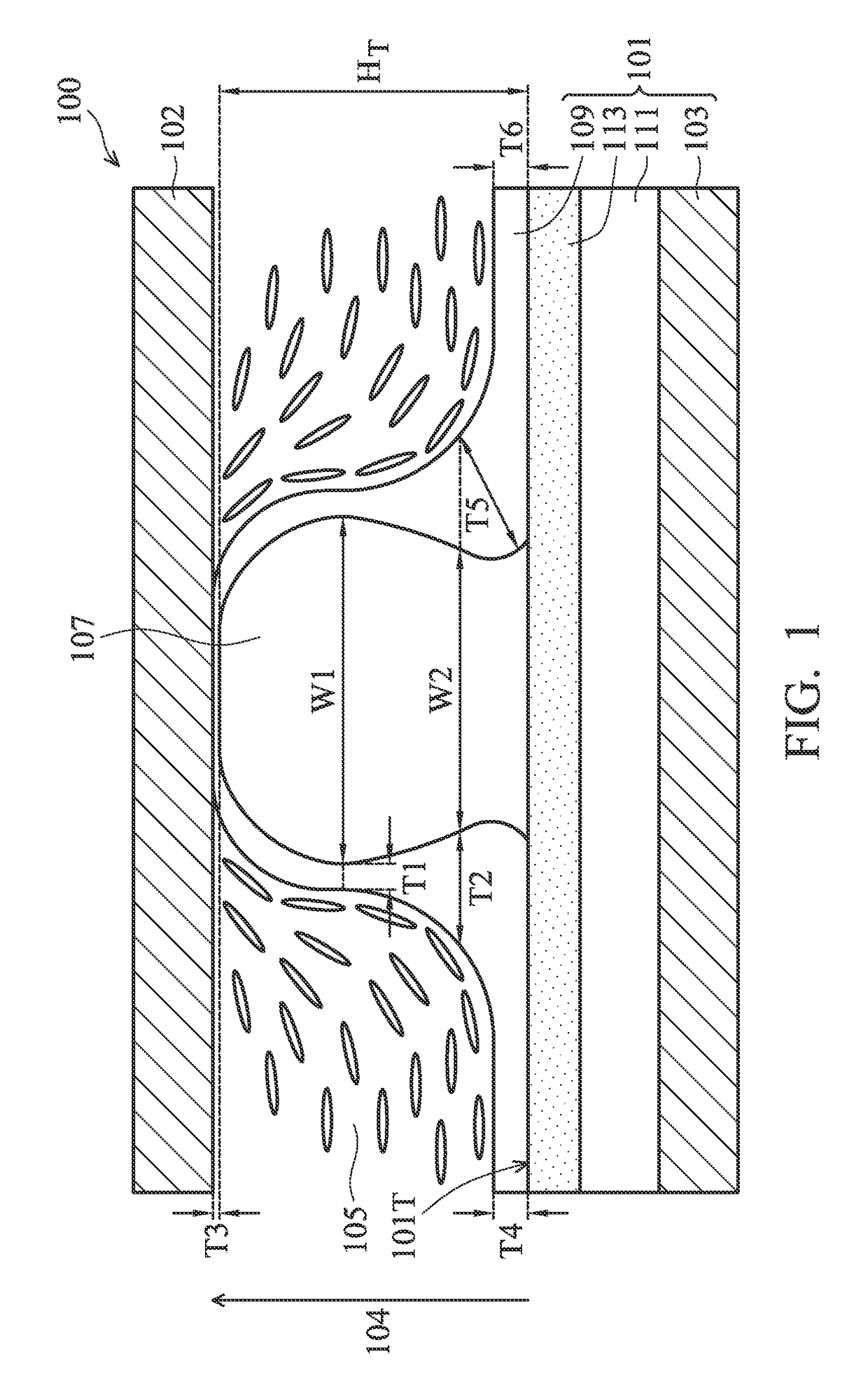
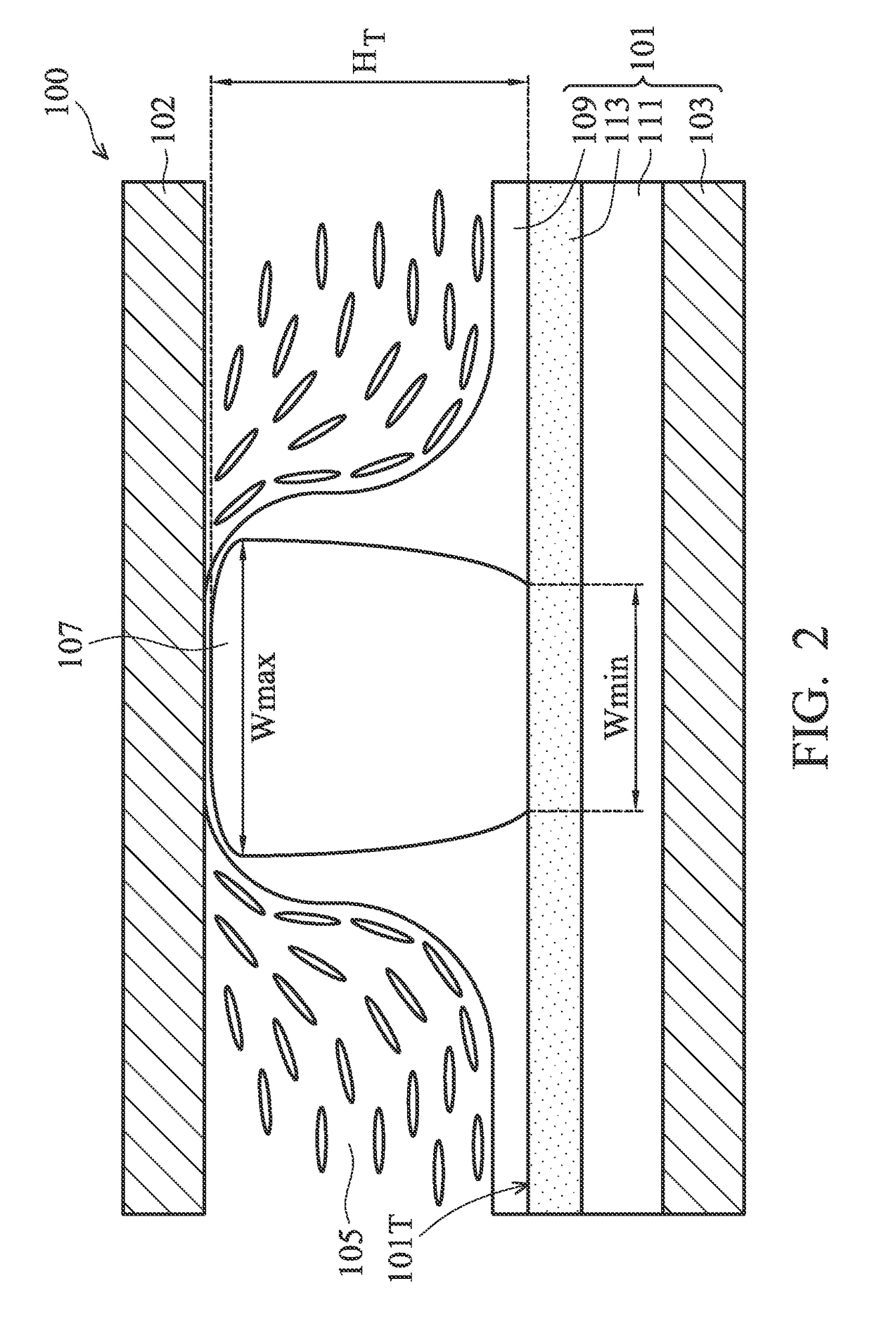
[0014]The following description is of the contemplated mode of carrying out some embodiments of display panels of the disclosure. This description is made for the purpose of illustrating the general principles of some embodiments of the disclosure and should not be taken in a limiting sense.

[0015]It is emphasized that, in accordance with the standard practice in the industry, various features in the accompanying drawings are not drawn to scale. The dimensions of the various features in the accompanying drawings may be arbitrarily increased or reduced for the sake of simplicity and clarity of discussion. Moreover, in the descriptions and the accompanying drawings of the embodiments that follow, the orientations of “on”, “over”, “above”, “under” and “below” are used for representing the relationship between the relative positions of each element in the display panels, and not used to limit the present disclosure. In fact, in the orientation of using the display panels, the CF substrat...


PUM

PropertyMeasurementUnit
widthaaaaaaaaaa
thickness T4aaaaaaaaaa
thickness T5aaaaaaaaaa

Abstract

A display panel includes a first substrate, a second substrate and a display medium. At least one spacer is formed on the top surface of the first substrate and is disposed between the first substrate and the second substrate. An alignment film is formed on the first substrate and covers the spacer. The spacer has a first width and a second width in a direction perpendicular to a normal vector of the first substrate. The location of the second width is nearer to the first substrate than that of the first width. The second width is smaller than the first width. The alignment film has a first thickness at the location of the spacer having the first width and has a second thickness at the location of the spacer having the second width. The second thickness is greater than the first thickness.

Description

CROSS REFERENCE TO RELATED APPLICATIONS[0001]This application claims priority of the Taiwan Patent Application No. 103138990, filed on Nov. 11, 2014, the entirety of which is incorporated by reference herein.BACKGROUND[0002]Field of the Invention[0003]The present invention relates to display panel technology, and in particular to spacers of display panels.[0004]Description of the Related Art[0005]Liquid-crystal display (LCD) panels are the primary component in plane displays. An LCD panel basically includes two glass substrates and a liquid-crystal layer sandwiched between the two glass substrates. The two glass substrates are a color filter (CF) substrate and a thin-film transistor (TFT) substrate, respectively. The CF substrate and the TFT substrate are spaced apart from each other by a certain distance. The liquid-crystal layer is filled in the space between the two substrates.[0006]In order to maintain the gap between the two substrates constant, bead spacers of uniform particle...

Claims


Application Information

Patent Timeline
Patent Type & Authority Patents(United States)
IPC IPC(8): G02F1/1339G02F1/1337
CPCG02F1/13394G02F1/133707
Inventor HSIAO, YI-CHENWANG, CHAO-HSIANGCHEN, YI-CHING
Owner INNOLUX CORP
Why Eureka
Try Eureka