
Plunger-type dispensing valve for the rapid deposition of adhesive to road pavement surfaces for enabling the fixation of pavement markers to road pavement surfaces

a technology of adhesive and dispensing valve, which is applied in the direction of valve operating means/releasing devices, functional valve types, valves, etc., can solve the problem that the valve needs to dispense adhesive materials extremely quickly, and achieve the effect of facilitating soft starts, minimizing the likelihood of formation, and minimizing the pressure prevailing at the valve member or shutoff blad

Active Publication Date: 2017-04-25
HOWSEMAN JR WILLIAM E
View PDF13 Cites 0 Cited by
  • Summary
  • Abstract
  • Description
  • Claims
  • Application Information

AI Technical Summary

Benefits of technology

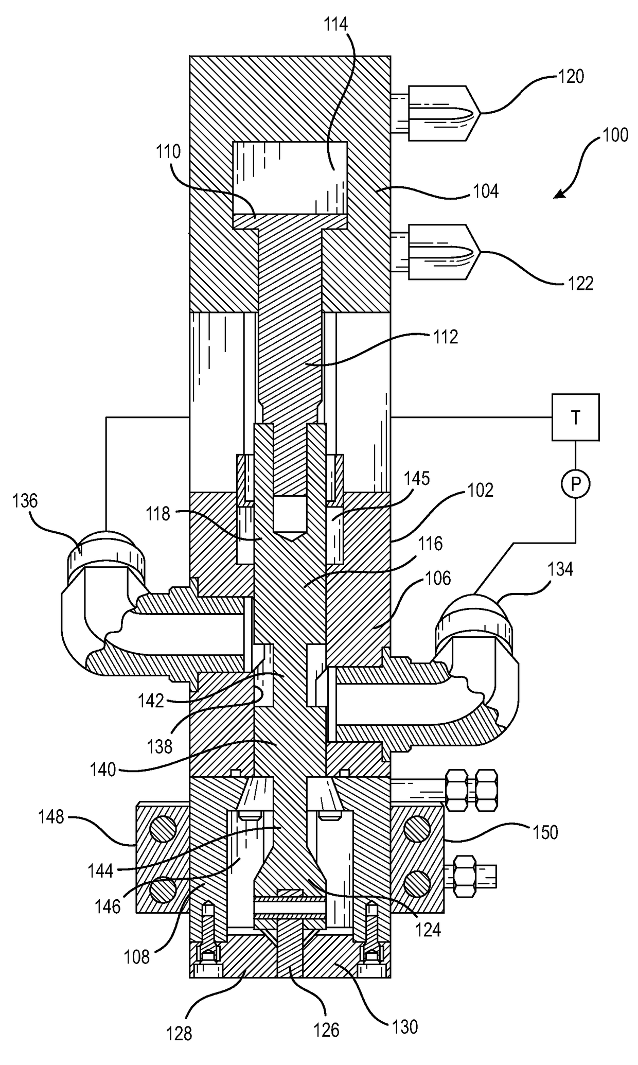
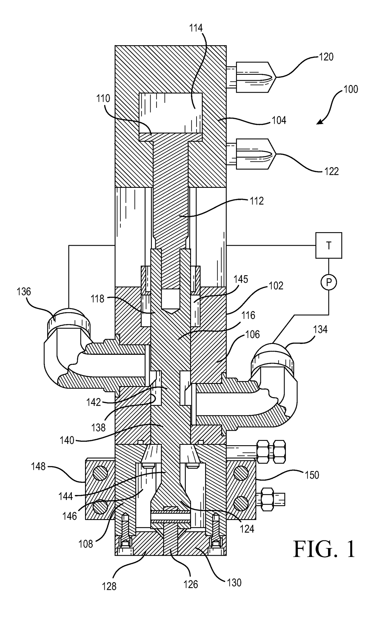
[0008]Accordingly, as will become more apparent hereinafter when reference is made to the accompanying drawings, when the valve plunger is disposed at its lowermost position whereby the valve member or shutoff blade is fully interposed between the pair of oppositely disposed shutoff outlet plates, or an alternatively configured valve seat, thereby defining the fact that the dispensing valve is disposed at its fully CLOSED position, the first upper annularly configured reduced diameter section of the valve plunger will effectively permit fluid communication between the adhesive material inlet supply port and the adhesive material outlet recirculation port such that the adhesive material is continuously recirculated throughout the system by means of a suitable pump operatively connected to an adhesive material reservoir or supply tank. The third intermediate enlarged diameter section of the valve plunger effectively prevents the adhesive material from flowing downwardly toward the dispensing or discharge output port, while the first uppermost enlarged diameter section of the valve plunger, in conjunction with a plunger rod seal annularly surrounding the first uppermost enlarged diameter section of the valve plunger, effectively prevents the adhesive material from flowing upwardly toward the piston-cylinder assembly.
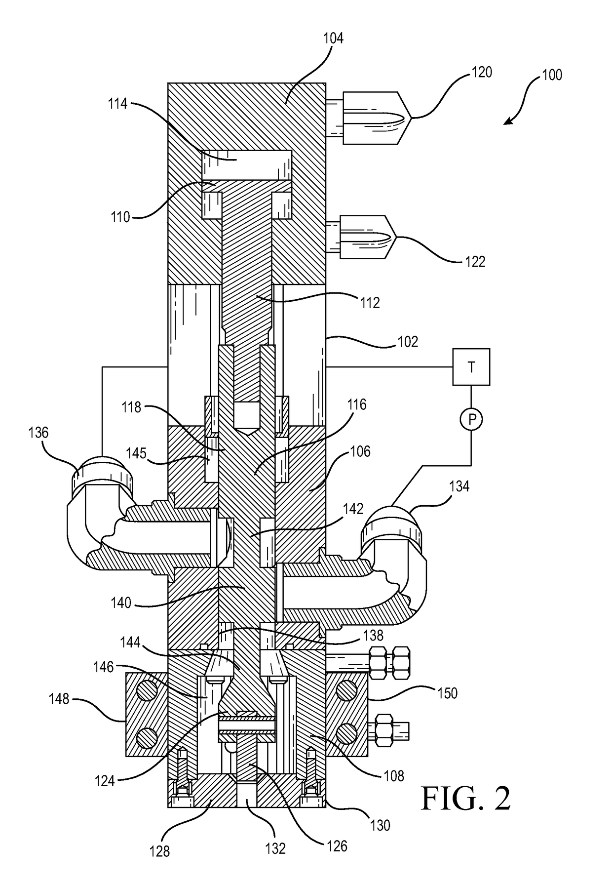
[0010]It is lastly to be noted that when the plunger valve is disposed at an intermediate TRANSITION position, that is at a position where the valve member or shutoff blade is only partially elevated and retracted away from the adhesive material dispensing valve output or discharge port, the third intermediate enlarged diameter portion of the valve plunger will be disposed directly opposite the adhesive material inlet supply port. Accordingly, all incoming fluid flow of the adhesive material is, at this point in time, blocked—all fluid flow of the adhesive material coming in from the adhesive material inlet supply port is zero, all fluid flow of the adhesive material to the adhesive material outlet recirculation port is zero, and all fluid flow of the adhesive material to the dispensing valve output or discharge port is likewise zero. This structure is extremely important in connection with the operation of the dispensing valve when the valve plunger is moved both from the fully CLOSED position to the fully OPEN position, as well as from the fully OPEN position to the fully CLOSED position, because, as will become more apparent hereinafter when reference is made to the drawings, the dispensing valve of the present invention effectively has dual shutoff locations, one at the adhesive material inlet supply port and one at the adhesive material output dispensing or discharge port. More particularly, this structure is extremely important in connection with the operation of the dispensing valve when the valve plunger is moved from the CLOSED position to the OPEN position because immediately before fluid flow is established from the adhesive material inlet supply port to the adhesive material output dispensing or discharge port, the prevailing line pressure at the adhesive material output dispensing or discharge port is minimal because the adhesive material inlet supply port, located upstream from the adhesive material output dispensing or discharge port, has been blocked or terminated by the disposition of the third intermediate enlarged diameter portion of the valve plunger being disposed directly opposite the adhesive material inlet port. This facilitates the achievement of “soft starts” or the dispensing of proper adhesive material outputs, as opposed to the deposition of excessive adhesive material outputs, because the relatively large line pressure does not immediately impact the adhesive material output dispensing or discharge port as would otherwise be the case if the relatively large line pressure was permitted to build up immediately behind the valve member or shutoff blade and to then be released when the valve member or shutoff blade is retracted so as to be moved to the fully OPEN position.
[0011]Alternatively, this structure also minimizes the likelihood of the formation of any residual material or splatter being discharged from the adhesive material output dispensing or discharge port when the valve plunger is moved from the fully OPEN position to the fully CLOSED position. This is because, just as was the fact that the valve member or shutoff blade was partially retracted vertically upwardly from its fully CLOSED position before the third enlarged diameter portion of the valve plunger was likewise moved vertically upwardly a sufficient distance so as to begin to OPEN the adhesive material inlet supply port, in this opposite directional movement scenario, wherein the valve plunger is being moved downwardly from its fully OPEN position to the fully CLOSED position, the third enlarged diameter portion of the valve plunger will fully block and close off the adhesive material inlet supply port before the valve member or shutoff blade is disposed at its fully CLOSED position. Accordingly, at this point in time, the line pressure prevailing at the valve member or shutoff blade is minimized, and as the valve member or shutoff blade seats or enters the adhesive material output dispensing or discharge port and terminates at a position flush with the undersurface portions of the adjacent shutoff outlet plates, it effectively pushes or forces any residual adhesive material out from adhesive material output dispensing or discharge port such that trailing ends or splatter of the adhesive material are minimized.

Problems solved by technology

In addition, the valve needs to dispense the adhesive material extremely quickly.

Method used


Image

  • Plunger-type dispensing valve for the rapid deposition of adhesive to road pavement surfaces for enabling the fixation of pavement markers to road pavement surfaces
  • Plunger-type dispensing valve for the rapid deposition of adhesive to road pavement surfaces for enabling the fixation of pavement markers to road pavement surfaces
  • Plunger-type dispensing valve for the rapid deposition of adhesive to road pavement surfaces for enabling the fixation of pavement markers to road pavement surfaces

Examples


Embodiment Construction

[0017]Referring now to the drawings, and more particularly to FIG. 1 thereof, the new and improved plunger-type dispensing valve is disclosed and is generally designated by the reference character 100. More particularly, it is seen that the dispensing valve 100 comprises a valve housing 102 wherein the valve housing 102 effectively comprises a first uppermost section 104, a second intermediate section 106, and a third lowermost section 108. A piston-cylinder assembly is disposed within the first uppermost section 104 of the valve housing 102 and is seen to comprise a piston which, in turn, comprises a piston head 110 and a piston rod 112, the piston head 110 being vertically movable within a cylinder portion 114 of the first uppermost section 104 of the valve housing 102. A lower end portion of the piston rod 112 is fixedly connected to a first uppermost enlarged diameter portion 116 of a valve plunger 118. The piston-cylinder assembly may be operated either pneumatically or hydraul...


PUM


Abstract

A reciprocating plunger-type valve mechanism or assembly, which can be utilized in conjunction with adhesive dispensing applicators to control the dispensing of adhesive compositions which are to be used in connection with the bonding, securing, or fixation of pavement markers to road pavement surfaces, is disclosed. The mechanism or assembly comprises dual shutoff locations in connection with the supply of the incoming adhesive material so as to effectively reduce the prevailing pressure upon the shutoff blade controlling the adhesive material dispensing / discharge port whereby soft pressure starts and controlled deposition quantities are enabled while the generation of residual adhesive material or splatter is avoided.

Description

FIELD OF THE INVENTION[0001]The present invention relates generally to dispensing valve mechanisms or assemblies, and more particularly to a new and improved reciprocating plunger-type dispensing valve mechanism which can be utilized in conjunction with adhesive dispensing applicators to control the dispensing of adhesive compositions which are to be used in connection with the bonding, securing, or fixation of pavement markers to road pavement surfaces.BACKGROUND OF THE INVENTION[0002]Pavement markers are conventionally applied to road pavement surfaces by means of a suitable adhesive. Various adhesive dispensing mechanisms are conventionally mounted upon a road vehicle that moves along a road pavement surface upon which the pavement markers are to be applied. The adhesive material is dispensed onto a predetermined location of the road pavement surface by means of the particular adhesive dispensing mechanism or apparatus, and subsequently, a technician / operator, riding upon the roa...

Claims


Application Information

Patent Timeline
Patent Type & Authority Patents(United States)
IPC IPC(8): B05C5/02F16K1/12F16K31/12F16K23/00F16K49/00B05C5/00E01C23/18
CPCB05C5/0237B05C5/001F16K1/126F16K23/00F16K31/12F16K49/00E01C23/18B05B1/304B05B1/3093F16K31/122F16K49/002
Inventor HOWSEMAN, JR., WILLIAM E.
Owner HOWSEMAN JR WILLIAM E
Learn More