Multi-gap rotating electric machine having phase coils formed of substantially U-shaped electric conductor segments

a technology of phase coils and electric conductor segments, which is applied in the direction of dynamo-electric machines, magnetic circuit rotating parts, magnetic circuit shape/form/construction, etc., can solve the problems of increasing manufacturing costs, and achieve the effect of effectively suppressing the torque ripple of the rotating electric machin

Active Publication Date: 2017-04-18
DENSO CORP
View PDF34 Cites 2 Cited by
  • Summary
  • Abstract
  • Description
  • Claims
  • Application Information

AI Technical Summary

Benefits of technology

[0011]With the above configuration, it is possible to form the phase coils of the stator coil by: (1) inserting the first and second leg portions of the electric conductor segments into the corresponding slots of the inner and outer core parts of the stator core from the one axial side of the rotor; (2) bending the distal end parts of the first and second leg portions of the electric conductor segments to form the radially inner coil end parts and radially outer coil end parts of the electric conductor segments; and (3) joining each corresponding pair of the radially inner coil end parts and each corresponding pair of the radially outer coil end parts. Further, with the above formation of the stator coil, it is possible to insert the first and second leg portions of the electric conductor segments into the corresponding slots of the inner and outer core parts of the stator core without passing the connecting portions of the electric conductor segments through the slots of the inner and outer core parts. Consequently, without the necessity of passing the connecting portions of the electric conductor segments through the slots of the inner and outer core parts of the stator core, it becomes possible to form each of the slots of the inner and outer core parts as a partially or fully closed slot. As a result, with the partially or fully closed formation of the slots of the inner and outer core parts, it becomes no longer necessary to set the numbers of the slots of the inner and outer core parts to be twice or more larger than usual for the purpose of suppressing torque ripple of the rotating electric machine. In other words, it becomes possible to effectively suppress torque ripple of the rotating electric machine with the numbers of the slots of the inner and outer core parts set to suitable values.
[0012]Moreover, with the above configuration, all the radially inner coil end parts and radially outer coil end parts of the electric conductor segments are formed on the same axial side of the stator core, thereby facilitating the process of joining the corresponding pairs of the radially inner coil end parts and radially outer coil end parts of the electric conductor segments.

Problems solved by technology

Consequently, with the increased numbers of the slots, the manufacture of the stator is complicated, thereby increasing the manufacturing cost.

Method used


Image

  • Multi-gap rotating electric machine having phase coils formed of substantially U-shaped electric conductor segments
  • Multi-gap rotating electric machine having phase coils formed of substantially U-shaped electric conductor segments
  • Multi-gap rotating electric machine having phase coils formed of substantially U-shaped electric conductor segments

Examples


first embodiment

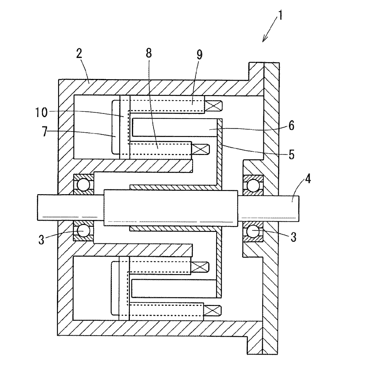
[0031]FIG. 6 shows the overall configuration of a multi-gap rotating electric machine according to a first embodiment.

[0032]In this embodiment, the multi-gap rotating electric machine is configured as a traction motor 1 to be arranged between an engine and a transmission in a hybrid vehicle.

[0033]As shown inFIG. 6, the motor 1 includes: a motor housing 2; a rotating shaft 4 that is rotatably supported by the motor housing 2 via a pair of bearings 3; an annular rotor 6 that is supported by the rotating shaft 4 via a rotor disc 5; a stator core that is fixed to the motor housing 2 and will be described in detail later; and a three-phase stator coil 7 mounted on the stator core.

[0034]The rotating shaft 4 is configured to be coupled to a crankshaft (not shown) of the engine either directly or via a clutch (not shown).

[0035]The rotor disc 5 is made, for example, of a nonmagnetic stainless steel. The rotor disc 5 is fitted on the outer periphery of the rotating shaft 4 so as to support th...

second embodiment

[0070]This embodiment illustrates a multi-gap rotating electric machine which has a similar configuration to the multi-gap rotating electric machine (i.e., the motor 1) according to the first embodiment; accordingly, only the differences therebetween will be described hereinafter.

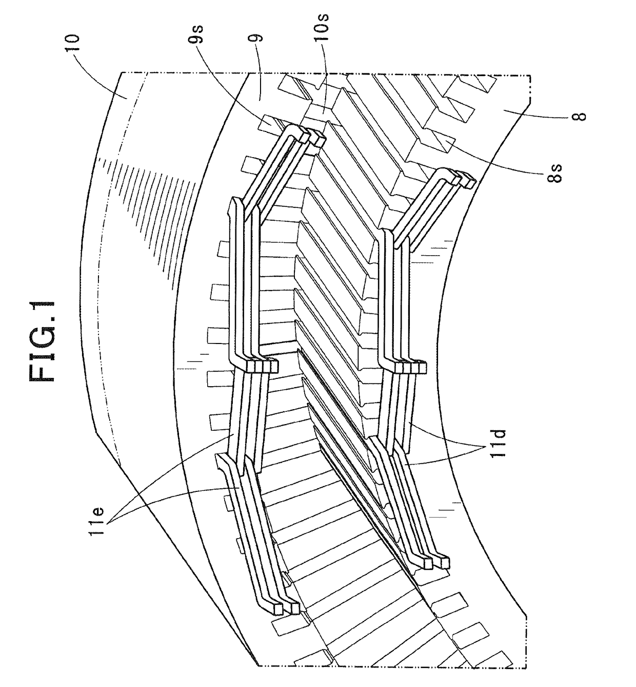
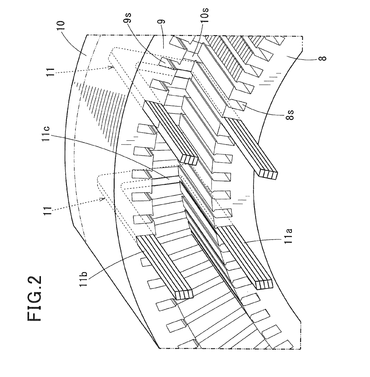
[0071]In the first embodiment, the side core part 10 of the stator core has the slots 10s formed therein, so that part of the electric conductor segments 11 have their respective connecting portions 11c received in the corresponding slots 10s of the side core part 10 (see FIGS. 4-5).

[0072]In comparison, in the present embodiment, as shown in FIG. 7, the side core part 10 of the stator core has no slots formed therein. Instead, the stator core part 10 is arranged on the one axial side (i.e., the left side in FIG. 7) of the rotor 6 so as to abut the connecting portions 11c of the electric conductor segments 11 that have their respective first and second leg portions 11a and 11b inserted in the corresponding s...

third embodiment

[0075]This embodiment illustrates a multi-gap rotating electric machine which has a similar configuration to the multi-gap rotating electric machine according to the first embodiment; accordingly, only the differences therebetween will be described hereinafter.

[0076]In the first embodiment, the stator coil 7 is comprised of the three phase coils that are star-connected to each other. In other words, the stator coil 7 includes only the single set of three phase coils.

[0077]In comparison, in the present embodiment, as shown in FIG. 8, the stator coil 7 is comprised of a first set of U-phase, V-phase and W-phase coils (to be referred to as a first coil unit 7A of the stator coil 7 hereinafter) and a second set of U-phase, V-phase and W-phase coils (to be referred to as a second coil unit 7B of the stator coil 7 hereinafter).

[0078]The U-phase, V-phase and W-phase coils of the first coil unit 7A of the stator coil 7 are star-connected to each other. The U-phase, V-phase and W-phase coils...


PUM


Abstract

A multi-gap rotating electric machine includes a rotor, a stator core and a stator coil. The stator core has inner and outer core parts respectively located radially inside and outside of the rotor and each having partially or fully closed slots. The stator coil is formed of electric conductor segments each having a first leg portion inserted in one of the slots of the inner core part, a second leg portion inserted in one of the slots of the outer core part, and a connecting portion connecting the first and second leg portions on one axial side of the rotor. The first and second leg portions respectively have radially inner and outer coil end parts formed on the opposite axial side to the connecting portion. Corresponding radially inner coil end parts are joined to each other, and corresponding radially outer coil end parts are joined to each other.

Description

CROSS-REFERENCE TO RELATED APPLICATION[0001]This application is based on and claims priority from Japanese Patent Application No. 2013-31183 filed on Feb. 20, 2013, the content of which is hereby incorporated by reference in its entirety into this application.BACKGROUND[0002]1. Technical Field[0003]The present invention relates generally to multi-gap rotating electric machines for use in, for example, motor vehicles. More particularly, the invention relates to a multi-gap rotating electric machine which is suitable for use as a high-performance and small-sized electric motor in a hybrid vehicle.[0004]2. Description of Related Art[0005]Japanese Unexamined Patent Application Publication No. 2012-80692, an English equivalent of which is US Patent Application Publication No. 2012 / 0080977 A1, discloses a multi-gap rotating electric machine.[0006]The multi-gap rotating electric machine includes a rotor and a stator. The rotor has an annular rotor core connected to a rotating shaft. The st...

Claims


Application Information

Patent Timeline
Patent Type & Authority Patents(United States)
IPC IPC(8): H02K16/00H02K3/28H02K16/04H02K21/14H02K3/12H02K19/10H02K21/22H02K1/16H02K16/02H02K1/27
CPCH02K3/12H02K19/103H02K3/28H02K21/14H02K21/22H02K1/16H02K1/27H02K16/025H02K16/04
Inventor FUKUSHIMA, AKIRAKUSASE, SHINMAEKAWA, TAKEOKONDOU, KEIJI
Owner DENSO CORP
Why Eureka
Try Eureka