
Retractable thruster

a technology of thrusters and assembly parts, which is applied in the direction of waterborne vessels, marine propulsion, vessel parts, etc., can solve the problems of unsuitable thrusters inclination with respect to the vertical axis, add additional weight, and bulky and heavy, and achieve the effect of reducing the overall dimension, simplifying the assembly construction, and minimizing the assembly weigh

Active Publication Date: 2017-04-18
FINCANTIERI
View PDF25 Cites 8 Cited by
  • Summary
  • Abstract
  • Description
  • Claims
  • Application Information

AI Technical Summary

Benefits of technology

[0027]By virtue of the provision of a watertight closed chamber, the present solution allows carrying out the maintenance of the propeller foot when the ship or platform is floating. By virtue of the possibility of evacuating the fluid, for example, sea water, it will be possible to carry out minor maintenance operations, for example, replacing the seals of the propeller foot, when the latter is arranged within the hull in said housing when the ship or platform is floating, maybe far from the shore or another dock.
[0028]The provision of a submersible movable hatch that is completely detachable from the thruster allows minimizing the assembly weight, hence of the structures interlocked to the retractable thruster, and it allows implementing a hull closing system to create an area, a watertight closed chamber, which is suitable to the maintenance and inspection of the thruster, which solution at the same time allows not to affect the thruster performance when this is extended to the exterior of the hull.
[0029]By virtue of the provision of a telescopic driving shaft, it is possible to implement a not very bulky assembly, which leaves the motor in a stationary position with respect to the hull, avoiding taking a considerable volume within the hull itself, which volume may be dedicated to other uses. Furthermore, by virtue of this solution, it is possible to avoid providing scaffoldings for the movement of motor components, considerably simplifying the construction of the assembly and reducing the overall dimensions while facilitating maintenance.
[0030]By virtue of the proposed solution, it is possible to increase safety during the maintenance steps, avoiding the build-up of dirt or incrustations in bulkheads or hatches suitable for a watertight closure, and in particular avoiding undesired infiltrations.
[0031]Advantageously, the provision of a submersible movable hatch in a separate piece and completely disconnected from the thruster and the housing allows, by virtue of scheduled maintenance operations, arranging only one closing hatch for multiple housings, so as to proceed with the maintenance of multiple retractable thrusters that are present on the same ship or platform through only one hatch.
[0032]Furthermore, the proposed solution is particularly advantageous, since it allows using the same handling means of the submersible movable hatch, also optionally to couple, hang and optionally lower the thruster, further increasing the constructive simplicity of the assembly, hence the safety of use.

Problems solved by technology

This known solution, while allowing the maintenance of the thruster when it is retracted within of the hull, is particularly bulky and heavy in all the steps of use thereof.
Particularly, the closing plate that is firmly secured to the thruster adds additional weight, as well as a drag of the ship for the entire time of normal use of the thruster in the extended position.
Of course, the presence of this closing plate secured to the thruster makes this solution unsuitable for thrusters inclinable with respect to the vertical axis, such as, for example the solutions described in the documents U.S. Pat. No. 7,641,526 and U.S. Pat. No. 4,580,517.
Therefore, the overall dimensions given by the closing plate and the ship drag thereof are a particularly felt problem.
Furthermore, in these applications, the substantially constant exposure of the closing plate to the substances that are present externally to the hull lead to a degradation of the plate portions that are suitable to the coupling with the hull, sometimes compromising the perfect coupling thereof to the hull.
For example, suppose how the effect of building-up incrustations may make the closure of the plate in contact with the bottom problematic and the risks following any water leakage into the cylindrical case into which the thruster is retracted for the maintenance thereof.
Therefore, this solution has necessarily to provide for the use of a, bulky interspace arranged vertically in the hull, which allows, in any time during the navigation, retracting the support scaffolding of the thruster motor within the hull itself, resulting in a considerable waste of volume within the hull, which volume the ship owner would like to be intended for other paying uses.
The presence of this plurality of retractable thrusters, implemented according this known solution, is not only particularly heavy, but moreover bulky and arranged in different areas of the hull, thus forcing to implement several vertical interspaces, which may sometimes reach the entire height of the same hull, segmenting the internal volume of the ship, thus making the use thereof still more complex.
However, no one of these documents proposes a solution to the above-mentioned drawbacks and needs.
Particularly, none of these solutions proposes a retractable thruster assembly that is as light-weighted as possible, not very bulky, and avoids any ship drag as much as possible, while ensuring at least the routine maintenance of the thruster when it is retracted within the hull.
Therefore, a particularly felt problem is to propose a thruster assembly for a ship or a floating platform, that allows the maintenance of the thruster itself when the ship or platform is floating, minimizing the weight and the overall dimensions of the structures interlocked to the retractable thruster.

Method used


Image

  • Retractable thruster
  • Retractable thruster
  • Retractable thruster

Examples


Embodiment Construction

)

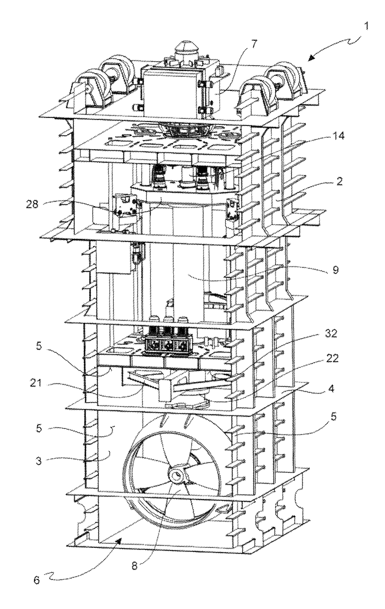
[0049]With reference to the above-mentioned Figures, a propulsion assembly of a ship or floating platform 1 comprises a hull insert 2, also referred to as a trunk, forming a housing 3, also referred to as a propeller case, located within a hull 4 of a ship or platform.

[0050]In accordance with an embodiment, said housing 3 is a housing watertight with respect to the hull in all the walls 5 thereof, except for an opening 6 opening externally to the hull 4 of the ship or platform.

[0051]Advantageously, said assembly further comprises a motor 7 and a thruster 8, for example a propeller foot.

[0052]In accordance with an embodiment, said thruster 8 is suitable to be arranged externally to said hull 4 to generate a propulsion thrust on said ship or floating platform. Said thruster 8 is further retractable within said housing 3 passing through said opening 6.

[0053]In accordance with an embodiment, said motor 7 is arranged in said hull 4, but externally to said housing 3, and it is arranged s...


PUM


Abstract

A propulsion assembly of a ship or floating platform includes a housing within a hull or platform. The housing is watertight except for an opening external to the hull. A stationary motor is arranged in the hull external to the housing. A thruster is external to the hull to generate thrust on the ship or floating platform. A telescopic driving shaft passes sealingly through a housing wall to connect the motor and the thruster and to transmit movement from the motor to the thruster. The thruster retracts within the housing through the opening. A separate submersible movable hatch is disconnectable from the thruster and the housing and passes externally to the hull, and seals the opening to form a watertight closed chamber. A fluid evacuation device evacuates fluid within the closed chamber so the thruster, when retracted in the housing and closed by the hatch, forms the closed chamber.

Description

[0001]This application is a National Stage Application of PCT / IB2014 / 059971, filed 19 Mar. 2014 which claims benefit of Serial No. MI2013A000694, filed 26 Apr. 2013 in Italy, and which applications are incorporated herein by reference. To the extent appropriate, a claim of priority is made to each of the above disclosed applications.FIELD OF THE INVENTION[0002]The present invention relates to a retractable thruster assembly of a ship or a floating platform.[0003]Particularly, the present invention relates to a retractable thruster assembly suitable to be maintained while the ship or the floating platform is at anchor, as well as in the case of a ship or platform that is floating.BACKGROUND OF THE ART[0004]Retractable thrusters or azimuthal retractable thrusters have been long known. The azimuthal thrusters are marine thrusters rotatable about a vertical axis (hence the name of azimuthal), thereby allowing the orientation of the propeller in any horizontal directions, making the pres...

Claims


Application Information

Patent Timeline
Patent Type & Authority Patents(United States)
IPC IPC(8): B63H5/125B63H21/36B63B17/00B63H5/14B63H25/42
CPCB63H5/1252B63B17/0018B63H5/125B63H5/14B63H21/36B63H2025/425B63H2005/1256
Inventor SCHIAFFINO, GIACOMOCALCAGNO, ALESSANDROBUCCI, STEFANOMAGNANO, GIOVANNI
Owner FINCANTIERI
Learn More